SPECIFICATIONS
SECTION 12 31 00.4
Manufactured Metal Casework
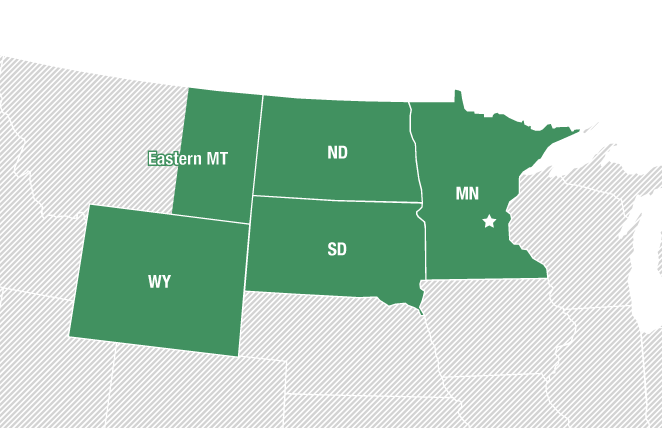
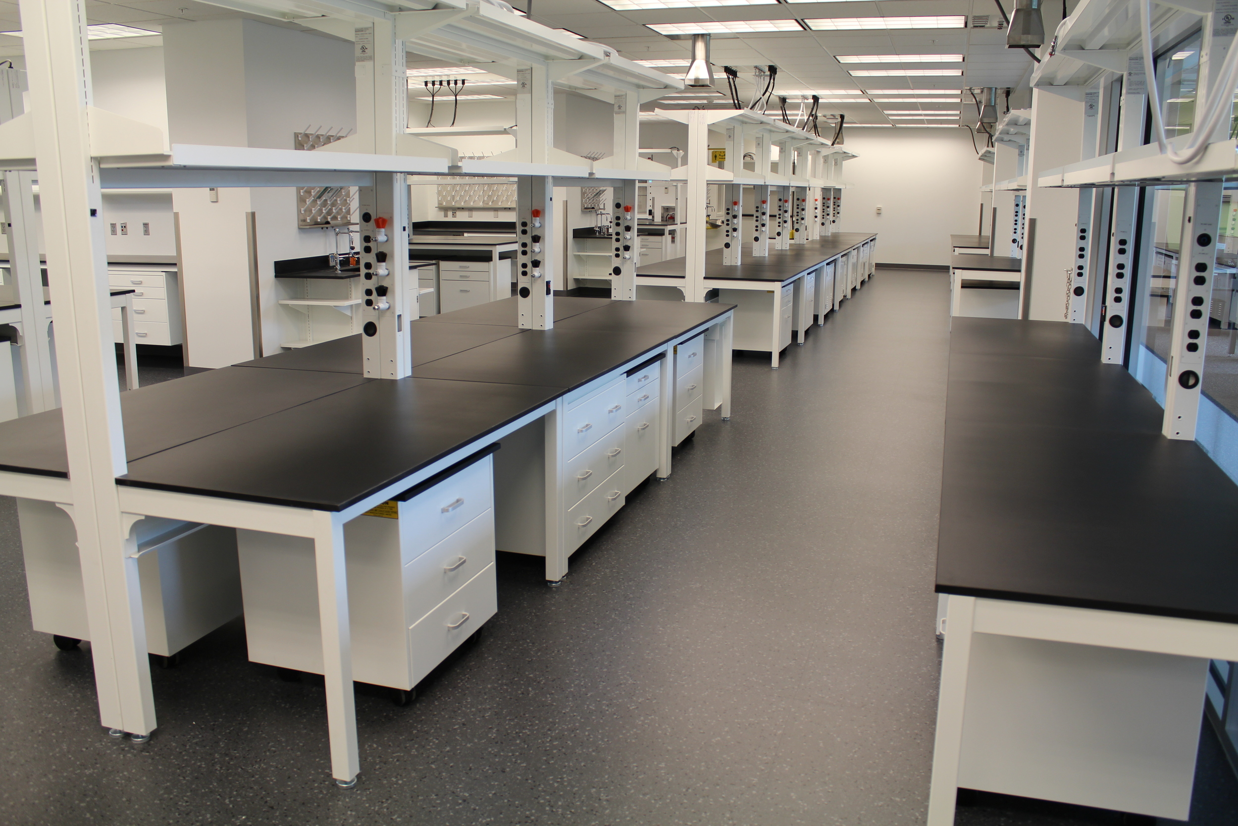
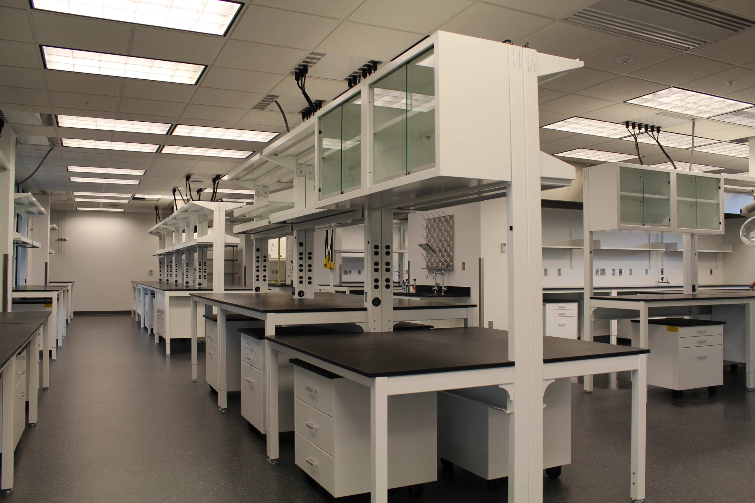
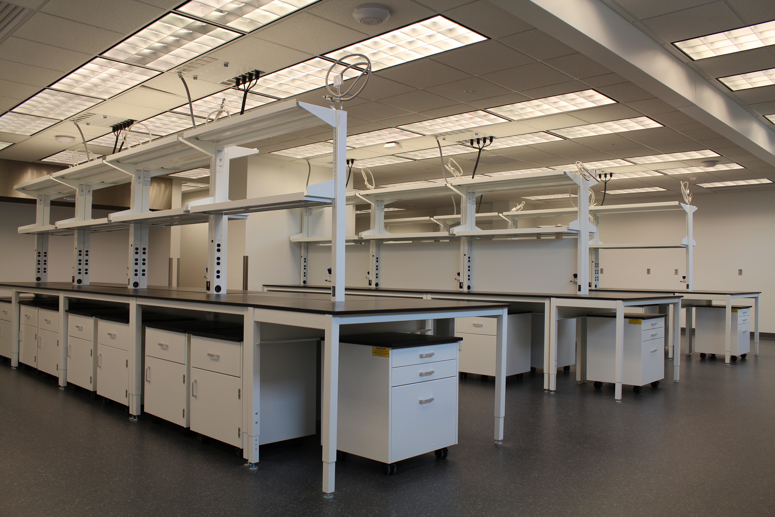
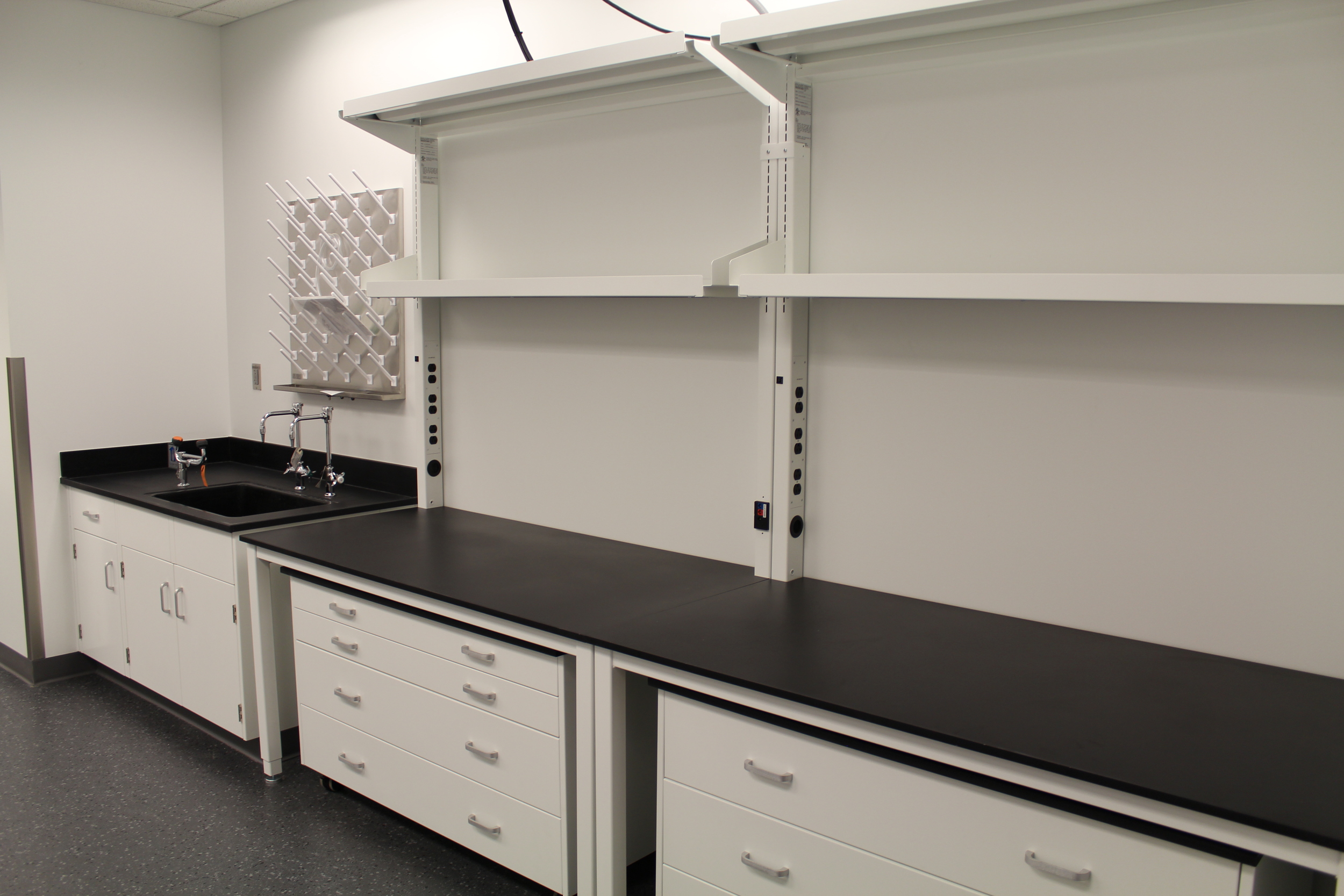
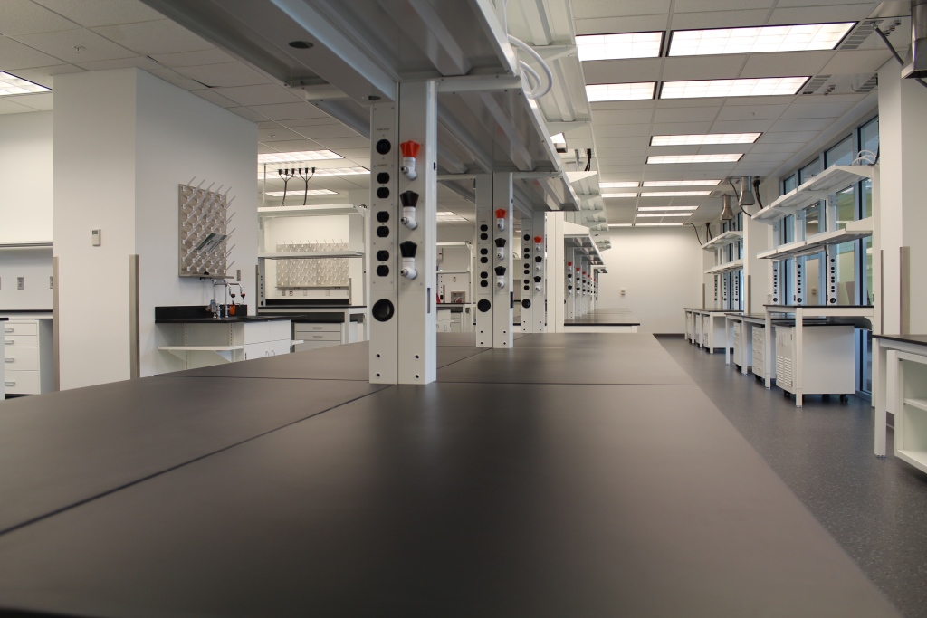
FLEXIBLE LABORATORY FURNITURE SYSTEM (ALTUS)
This section is based on the products of Mott Manufacturing Ltd., which is located at:
452 Hardy Rd
Brantford, ON N3T 5L8
T (519) 752-7825
Email: inquire@mott.ca
www.mott.ca
SECTION 12 31 00 – FLEXIBLE LABORATORY FURNITURE SYSTEM (ALTUS)
PART 1 – GENERAL
1.1 SECTION INCLUDES
A. Modular Support Structure and Structural Table Base
B. Mobile Base / Wall Cabinets and Shelves
C. Fixtures and related Service Connections
1.2 RELATED SECTIONS
A. Division 06 Section 10 00, “Rough Carpentry”
B. Division 06 Section 40 00, “Architectural Woodwork”
C. Division 11 Section 53 00, “Laboratory Equipment”
D. Division 12 Section 36 00, “Countertops”
E. Division 12 Section 35 53, “Manufactured Metal Casework
F. Division 12 Section 32 00, “Manufactured Wood Casework”
G. Division 22 Section 40 00, “Plumbing Fixtures”
H. Division 26 Section 05 00, “Common Work Results for Electrical”
I. Related Work To Be Performed By Others:
1. Final installation and connection of all plumbing, service and electrical fixtures attached to service carriers.
1.3 REFERENCES
A. SEFA 8: Laboratory Furniture – Casework, Shelving and Tables Guidelines
B. ISO 9001:2008 – Quality Management International Standards Organization (ISO)
C. ADA (ATBCB ADAAG) Americans with Disabilities Act Accessibility Guidelines
1.4 SUBMITTALS
Refer to Section 01 33 00, “Submittal Procedures,” for requirements, procedures, etc.
A. Product Data:
1. Drawings to include data and details for construction of the laboratory furniture. Further, provide name, quantity, type and construction of materials (such as hardware, gauges, etc).
B. Shop Drawings:
1. Provide shop drawings showing the layout and placement of all products by this section.
2. Show the type and location of all service fittings by this section.
3. Preparation instructions and recommendations.
4. Storage and handling requirements and recommendations.
C. Selection Samples:
1. Submit: one complete set of color chips showing the manufacturer’s full range of colors. Minimum sample size: 2” x 2-1/2”.
D. Quality Assurance/Control
1. Design Data/Test Reports: Submit test data and design criteria in compliance with the project specifications.
1.5 QUALITY ASSURANCE
A. Manufacturer Qualifications:
1.5 Provide to the Architect at least ten days prior to the bid opening:
1. List of manufacturing facilities.
2. Construction details depicting the materials, sizes and methods of construction.
B. Mock-Ups
1. Area mockups to be as indicated on the shop drawings. Include cost for post-bid mockup including installation and reinstallation for use within the project.
2. Do not proceed with remaining work until installation is approved by Architect.
3. Install service carrier post, body and all supports and cover panels as required.
1.6 DELIVERY, STORAGE AND HANDLING
A. Packaging, Shipping, Handling and Unloading
1. Products to have packaging adequate to protect finished surfaces from soiling or damage during shipping, delivery and installation.
2. Delivery: Casework delivery to take place after painting, utility rough-ins and related activities are completed that could otherwise damage, soil or deteriorate casework in installation areas.
3. Handling: Use proper moving equipment and personnel at all times. Any wrapping or other method of protection to be left in place to avoid damage.
B. Acceptance at Site:
1. Casework is not to be delivered or installed until the conditions specified under Part 3, Installation, have been met.
C. Storage:
1. Casework to be stored in the area of installation. If it is necessary for casework to be temporarily stored in an area other than the installation area, the environmental conditions to meet the environmental requirements specified under the Project Site Conditions article of this section.
D. Waste Management and Disposal:
1. Remove any waste or refuse resulting from the installation of laboratory casework. Leave the project site broom clean and free of debris. Trash container(s) to be provided by others.
1.7 PROJECT SITE CONDITIONS
A. Building must be enclosed. Windows and doors sealed and weather-tight.
B. An operational HVAC system that maintains temperature and humidity at occupancy levels must be in place.
C. Adjacent and related work to be complete.
D. Ceiling, overhead ductwork and lighting must be installed.
E. Site must be free of any further construction such as “wet work”.
F. Required backing and reinforcements must be installed accurately and the project must be ready for casework installation.
1.8 WARRANTY
A. Furnish a written warranty that work performed under this section to remain free from defects as to materials and workmanship for a period of two years from date of shipment. Defects in materials and workmanship that develop within this time are to be replaced without cost or expense to the Owner.
B. Defects include, but are not limited to:
1. Ruptured, cracked, or stained coating
2. Discoloration or lack of finish integrity
3. Cracking or peeling of finish
4. Slippage, shift, or failure of attachment to wall, floor, or ceiling
5. Weld or structural failure
6. Warping or unloaded deflection of components
7. Failure of hardware
C. The warranty with respect to products of another manufacturer sold by Mott Manufacturing is limited to the warranty extended by that manufacturer to Mott Manufacturing.
PART 2 – PRODUCTS
2.1 MANUFACTURER
A. Acceptable Manufacturer: Mott Manufacturing Ltd.; 452 Hardy Rd. Brantford, ON, Canada N3T 5L8. T (519) 752-7825. Email: inquire@mott.ca, www.mott.ca.
B. Substitutions must meet all specification requirements and have prior approval.
C. Substitutions must meet the minimum design and performance requirements of SEFA and UL 962.
D. Requests for substitutions: All requests will be considered in accordance with provisions of Section 01 60 00.
2.2 MATERIALS
A. Sheet Steel: Mild steel, cold rolled furniture grade to requirements of ASTM A1008/A1008M, Grade C or higher.
B. Galvanized Sheet Steel: Commercial quality, to ASTM 653, Designation Z275.
C. Stainless Steel: to ASTM A240, T304 and T316 alloy, #4 brushed finish.
D. Glass: .” thick with steel frame work to protect edges.
2.3 DESIGN REQUIREMENTS:
*Basis of design: Mott Manufacturing Altus Series Table system*
A. Modular system to be made of tubular style framing combined with rectangular formed steel uprights.
B. Tubular Frames / Table Supports to be adjustable height in 1” increments and complete with levelers.
C. Rear frame to be used for carrying services and electrical conduit.
1. Rear upright supports to be equipped with slots for adjustable shelving and levelers.
2. All services supplied with hose and quick disconnect to reach ceiling panel supply.
D. Assembled frame to be self-supporting without needing to be anchored to the building.
E. The modular system must ship complete from the factory with minimal on-site assembly.
2.4 ALTUS CONSTRUCTION
A. Rear Support Structure:
1. Nominal rear frame dimensions: Width: 48”, 60”, 72”, Depth: 3", Height: 84”
2. Rear Uprights:
a. 2” x 3” 14 ga. powder coated cold rolled steel or stainless steel.
b. 2” diameter nylon leveling glide 3/8” x 2-1/2” long threaded stem.
3. Upper Cross Rail: 16 ga. powder coated cold rolled steel or stainless steel.
4. Load Capacity: Rear Upright to support up to 3 shelves loaded to a combined maximum of 300lbs. Shelf depths available as 12” or 15” deep.
5. Uprights to house services, electrical and data cables: High voltage cabling to be in a separate upright from gas piping.
6. Wire management tray to be under countertop.
7. Rear posts have slots punched on 1” increments starting at nominal 59” above the finished floor.
B. Tubular Table Assembly:
1. Nominal table assembly dimensions:Width: 48”, 60”, 72”, Depth: 23” or 29”, Height: Adjustable from 29” – 36” (not including work surface).
2. Tubular Table Legs:
a. 2” outside square, 14ga. powder coated cold rolled steel or stainless steel outer leg.
b. 1-.” outside square, 11ga. powder coated cold rolled steel or stainless steel inner telescoping leg.
c. 2” diameter nylon leveling glide 3/8” x 2-1/2” long threaded stem
3. Capable of vertical height adjustment in 1” increments.
4. Table assembly to be fastened to the rear upright with two (2) hex 3/8” socket head bolts.
5. Hanging Rails: Front apron and rear support are to have rails allowing suspended cabinets to hang from.
6. Leveling Bolt: Frame to be fitted with a leveling bolt which will allow the legs to be adjusted for proper alignment of work surface height.
7. Load Capacity: Table frame to support 1000lbs including the work surface.
C. Shelves:
1. Nominal shelf dimensions: Width: 48”, 60”, 72”. Depth: 12” or 15” for shelves. 1” thick.
2. Shelf requirements:
a. Shelves constructed of powder coated cold rolled steel, or stainless steel.
b. Wood Shelves are only available for table widths up to 60”.
c. Shelves to be flush with the face of the rear rectangular posts.
d. Shelf brackets to be constructed powder coated cold rolled steel or stainless steel.
e. Bottom and middle shelves to have a rear 1” high retaining lip. Top shelf assemblies do not come with retaining lip.
f. Vertical shelf adjustment in 1” increments.
g. Optional 1” tall x 5/16” dia. shelf retainer rods, available in #304 stainless steel or #304 powder coated stainless steel.
D. Suspended/Mobile Base Cabinets:
1. Design and construction to be as in section 12 35 53 - Laboratory Metal Casework and 12 35 53 – Laboratory Wood Casework.
2. Mobile cabinets to have casters in lieu of a toe kick. Casters to all be rated for 165lbs minimum each and to be locking type. Cabinet height must ensure 2-. ” of clearance under the table frame.
3. Suspended base cabinets: Provide a system of steel hanger rails attached to the casework frames. Installation and removal to be accomplished without the use of tools.
E. Plumbing/Fixtures:
1. Rear upright structure to support a maximum of three plumbing fixtures on left side.
2. Fixtures to be needle valve style with a single serrated hose end angled towards front of bench. Additional valve fixture hole angled towards the rear of the bench is to be capped for potential future use.
3. Plumbing lines to be polyurethane routed out the top of the upright.
4. All burning gas tubing to be specified as stainless steel.
5. All plumbing to have service hose at the top of the upright with additional 4’ of hose length to reach the ceiling supply panel.
6. Plumbing to be arranged that they services cannot be intermixed.
7. All service valves and quick disconnects to be keyed and color coded. Only plug and body connects of the same key will couple and allow flow.
F. Service Connections:
1. Electrical, data and plumbing services to terminate with cable or hose coming out of the top of the rear support upright.
2. Electrical services to have a 20 amp cord extending 4’ above the top of the upright.
3. Data services to have a male plug extending 4’ above the top of the upright.
G. Ceiling Service Panels:
1. Panels to be compatible with most T-grid acoustical suspended ceiling structures.
2. Panel to provide a means to mount and disconnect quick connect service fixtures, electrical and data outlets.
3. Panel to accommodate single sided and back to back bench configurations.
4. Panels ship with cover plates. Data outlets, electrical outlets, junction boxes and service fixtures to be ordered separately.
5. Panels to be 23-.” x 23-.” x 1”, 14 gauge cold rolled steel with a powder coated finish.
2.6 STEEL FURNITURE FINISH
1. Metal finish to be as in Appendix 1 - Laboratory Steel Furniture Finish.
PART 3 – EXECUTION
3.4.1 INSTALLATION
1. Install casework within system, align and set level with leveling devices, in accordance with shop drawings.
2. At wall locations secure wall cabinets to face of finished walls and partitions, applying self-tapping screws through wall finish material into each concealed stud flange.
3. Install components to effect a secure, neat and complete installation.