SPECIFICATIONS
SECTION 11 53 13
(FORMERLY 11610)
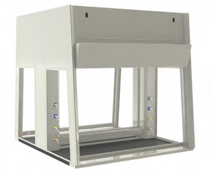
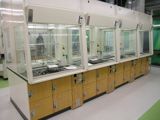
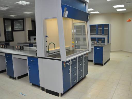
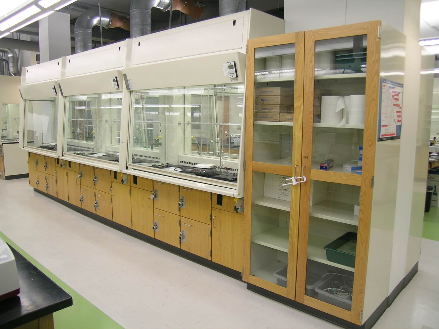
OBSERVATION2 STYLE GLASS WALLED FUME HOODS
SECTION 11 53 13 – LABORATORY FUME HOODS
PART 1 – GENERAL
Summary:
This Specification identifies the minimum material and construction standards that are required to deliver a quality installation of laboratory fume hoods. Fume hoods shall be supplied in accordance with the requirements of this Specification. The fume hoods identified in this Specification shall include the miscellaneous metal panels and other related components as identified on the Drawings and that are necessary for the complete installation.
Hoods shall function as ventilated, enclosed work spaces, designed to capture, confine and exhaust fumes, vapours and particulate matter produced or generated within the enclosure. Observation2 fume hoods are not suited to highly corrosive situations.
1.1 SECTION INCLUDES
- Laboratory Fume Hoods
1.2 RELATED SECTIONS
** NOTE TO SPECIFIER ** Delete sections below that are irrelevant to project. Add sections as required.
A. Division 09 Section 65 13, “Resilient Base and Accessories”
B. Division 12 Section 36 00, “Countertops”
C. Division 12 Section 35 53, “Manufactured Metal Casework
D. Division 12 Section 32 00, “Manufactured Wood Casework”
E. Division 13 Section 21 00, “Controlled Environment Rooms”
F. Division 22 Section 40 00, “Plumbing Fixtures”
G. Division 23 Section 30 00, “HVAC Air Distribution”
H. Division 26 Section 05 00, “Common Work Results for Electrical”
I. Related Work To Be Performed By Others:
1. Final installation of all plumbing, service and electrical fixtures attached to fume hood or countertop (excluding piping and wiring within fume hoods).
2. Final connection to service lines of all plumbing, service and electrical fixtures attached to laboratory casework or fume hoods.
1.3 REFERENCES
** NOTE TO SPECIFIER ** Delete references below not required for project.
- SEFA 1-2010: Laboratory Fume Hoods – Design, Materials, Use and Testing Guidelines
Science Equipment and Furniture Association (SEFA)
- ISO 9001:2008 – Quality Management
International Standards Organization (ISO)
- ADA (ATBCB ADAAG) Americans with Disabilities Act Accessibility Guidelines
Americans with Disabilities Act (ADA)
D. ANSI/ASHRAE: (American National Standards Institute - American Society of Heating, Refrigerating and Air Conditioning Engineers)
E. UL 1805: Underwriters Laboratories requirements for ducted fume hoods
1.4 SUBMITTALS
Refer to Section 01 33 00, “Submittal Procedures,” for requirements, procedures, etc.
- Product Data:
1. Drawings shall include data and details for construction of the laboratory fume hoods as well as information regarding the name, quantity, type and construction of materials (such as hardware, gauges, etc), that will be used to complete the project.
- Shop Drawings:
1. The laboratory casework manufacturer shall furnish shop drawings illustrating the layout and placement of all laboratory casework and fume hoods as well as any products included in this section.
2. Indicate the type and location of all service fittings and associated supply connections.
3. Preparation instructions and recommendations.
4. Storage and handling requirements and recommendations.
5. Installation methods.
- Selection Samples:
1. One complete set of color chips representing the manufacturer’s full range of available colors. Minimum sample size 2 inches by 2-1/2 inches (50mm x 64mm).
- Quality Assurance/Control
1. Design Data/Test Reports: Manufacturer shall submit test data and design criteria which are in compliance with the project specifications.
2. Performance: Fume Hoods, Sigma Systems “Observation2” model, shall be designed to meet or exceed the American Standard for Laboratory Ventilation and the American Industrial Hygiene Association standard as described in ANSI/AIHA Z9.5. This standard of performance shall be verified through factory testing in accordance with the established protocol as set out by the ANSI/ASHRAE 110 standard.
3. UL 1805 listed for fume hood requirements as specified and tested.
4. Certificates: All certifications required in the specifications shall be submitted with the original submittal package under separate cover. Certificates must be provided with the signature of a qualified individual of the supplier.
5. Manufacturers’ Instructions: Provide manufacturer’s instructions for installation and maintenance of all products provided and installed within this section.
6. Submit copy of the corrosion resistant label to be attached to the fume hood exterior with condensed information covering recommended locations for apparatus and accessories.
1.5 QUALITY ASSURANCE
- Manufacturer Qualifications:
1. The following list of information will be provide to the Architect at least ten (10) days prior to the bid opening:
2. List of manufacturing facilities
3. Manufacturer of fume hoods shall have the capability within their facility of performing fume hood tests based on the latest ANSI/ASHRAE Specification 110.
4. A list of ten (5) installations of comparable stature completed within the past 5 years
5. Construction details depicting the materials, sizes and methods of construction
- Mock-Ups
** NOTE TO SPECIFIER ** Include a mock-up if the project size and/or quality warrant taking such a precaution. The following is one example of how a mock-up on a large project might be specified. When deciding on the extent of the mock-up, consider all the major different types of work on the project.
1. Area mockups shall be as indicated on the shop drawings. Post bid mockup areas must be priced for disassembly and reassembly and used within the project.
2. Do not proceed with remaining work until installation is approved by Architect.
a) Install base cabinet with specified hardware.
b) Install fume hood with specified fixtures.
1.6 DELIVERY, STORAGE AND HANDLING
- Packaging, Shipping, Handling and Unloading
1. Packaging: Products shall have packaging adequate enough to protect finished surfaces from soiling or damage during shipping, delivery and installation.
2. Delivery: Fume hood delivery shall only take place after painting, utility rough-ins and related activities are completed that could otherwise damage, soil or deteriorate fume hoods in installation areas.
3. Handling: Care, such as the use of proper moving equipment, experienced movers, etc., shall be used at all times to avoid damaging the fume hoods. Until installation takes place, any wrapping, insulation or other method of protection applied to products from the factory will be left in place to avoid accidental damage.
- Acceptance at Site:
1. Fume hoods will not be delivered or installed until the conditions specified under Part 3, Installation section of this document have been met.
- Storage:
1. Fume hoods shall be stored in the area of installation. If, prior to installation, it is necessary for the fume hoods to be temporarily stored in an area other than the installation area, the environmental conditions shall meet the environmental requirements specified under the Project Site Conditions article of this section.
- Waste Management and Disposal:
1. The supplier of the laboratory fume hoods are responsible for removing any waste or refuse resulting from the installation of, or work pertaining to laboratory fume hoods; thereby leaving the project site clean and free of debris. Trash container(s) to be provided by others.
1.7 PROJECT SITE CONDITIONS
A. Building must be enclosed (windows and doors sealed and weather-tight).
B. An operational HVAC system that maintains temperature and humidity at occupancy levels must be in place.
C. Adjacent and related work shall be complete.
D. Ceiling, overhead ductwork and lighting must be installed.
E. Site must be free of any further construction such as “wet work”.
F. Required casework must be installed accurately and the project must be ready for fume hood installation.
1.8 WARRANTY
A. Furnish a written warranty that Work performed under this Section shall remain free from defects as to materials and workmanship for a period of two (2) years from date of shipment. Defects in materials and workmanship that may develop within this time are to be replaced.
Defects include, but are not limited to:
1. Ruptured, cracked, or stained coating
2. Discoloration or lack of finish integrity
3. Cracking or peeling of finish
4. Slippage, shift, or failure of attachment to wall, floor, or ceiling
5. Weld or structural failure
6. Warping or unloaded deflection of components
7. Failure of hardware
B. The warranty with respect to products of another manufacturer sold by Mott Manufacturing is limited to the warranty extended by that manufacturer to Mott Manufacturing.
PART 2 – PRODUCTS
2.1 MANUFACTURER
** NOTE TO SPECIFIER ** Delete or modify the following paragraphs to coordinate with the Owner’s requirements.
A. Acceptable Manufacturer:
Mott Manufacturing Ltd.; 452 Hardy Rd. Brantford, ON, Canada N3T 5L8. Tel: (519) 752-7825 Fax: (519) 752-2895. Email: inquire@mott.ca, www.mott.ca.
Basis of Design: Mott Manufacturing Observation2 Fume Hood
B. Substitutions:
Must meet all specification requirements and have prior approval.
C. Requests for substitutions:
All requests will be considered in accordance with provisions of Section 01 60 00.
2.2 FUME HOOD MATERIALS
- Basic Materials
NOTE: A complete list of basic materials is provided here. Not all models use all materials listed.
1. Exterior Panels Framing Members, and Furring Panels: Cold rolled and leveled mild steel and shall conform to ASTM A1008/A1008M, finished as in Para. 2.4.
2. Screws: Interior fastening devices; stainless steel screws.
3. By-Pass: 18 Ga (1.2mm) thick mild steel downward directional, finished same as exterior panels.
4. Upper front panel: to be 20 Ga (0.9mm) thick mild steel powder coated that is removed without the use of tools and doesn’t have any exposed screws.
5. Lower Foil / Flush Sill: Type 316-4 stainless steel powder coated.
6. Safety Glass: All glass panels shall be laminated type ¼” (6mm) thick.
7. Sash guides: Track shall be corrosion resistant polyvinyl chloride (PVC).
8. Sash Chain: #35 hardened.
9. Sash Pull: Type 316, 18 Ga (1.2mm) thick stainless steel with an ANSI #4 satin finish.
10. Sprocket System For Sash Chain: Sprockets with one full width shaft per sash running in ball bearings.
11. Baffle/plenum: Interior to chamber shall be 18 Ga. metal per either of the following with no exceptions:
i. Mild cold rolled steel that has been galvanized or galvannealed and powder coated to match the rest of the fume hood.
ii. Type 316 stainless steel that is powder coated to match the rest of the hood.
12. Duct Stubs: Rectangular Type 316, 18 Ga (1.2mm) stainless steel.
13. Light Switch: Light switch shall be combination style with one NEMA 5-20R receptacle, white in color, commercial spec grade or higher and shall be UL and CSA approved and shall located in the left side post.
14. Electrical receptacles: Electrical receptacles shall be white combination style with two NEMA 5-20R receptacles and two USB charging receptacles in each, and be UL and CSA approved and shall be located in the bottom of the right side post.
15. Fluorescent Light: Fixture shall be two tube rapid start or better. Energy saving cool white T8 lamps shall be provided. Ballast shall be sound rated to limit noise.
- Fume Hood Interior
1. Interior shall be powder coated 18 Ga. galvanized or galvannealed mild cold rolled steel to
match the rest of the fume hood. Optional 316 stainless steel liner is also available.
- Fume Hood Furring Panels
1. Where called for, provide matching furring panels to enclose the space between top edge of fume hoods and the finished ceiling.
2. Panels shall be flanged, notched and reinforced where required to form a well-fitted enclosure, free from oil canning. Panels shall be held in place with hidden snap clips and shall be easily removable for maintenance purposes. Exposed screw heads are not acceptable.
3. Finish shall match fume hood to which it is connected.
2.3 FUME HOOD CONSTRUCTION
A. Units may be double or single chamber. Single-face fume hoods shall have a sloped sash (optional combination sash). Double-face fume hoods shall have both sashes sloped (optional combination sashes). Specification applies to both single-faced and a double-faced hood however only reads as single-faced for clarity.
B. Fume hood superstructure shall be single wall construction consisting of sheet steel and laminated safety glass.
C. Bottom/Side walls shall be designed to accept service outlets.
D. Interior members shall be fastened by means of exposed and concealed screws.
E. Exterior members shall be fastened by means that conceal all screws. Exposed screws are not acceptable. Snap-off top panel, and front post covers shall be easily removable with the use of simple hand tools.
F. Provide access to remote-controlled front load fixture valves through front post and interior removable panel. A maximum of four plumbing fixtures shall fit in each post and shall ship pre-plumbed from the factory using 3/8” OD cross linked polyethylene tubing with the exception of natural gas which shall be stainless steel tubing. Front posts shall be 3” wide and 4-1/2” deep to maximum sash width and side wall window area. Remote-controlled ball type or rod type valves must be mounted below the hood. Ball type or rod type fixtures will not ship pre-plumbed from the factory.
G. Install fluorescent lighting fixture on exterior of roof. Provide a 6mm (1/4”) safety glass panel on hood "roof", sealed to isolate the lighting fixture from fume chamber. The 2-lamp fixture in each hood shall be largest possible for fume hood size. Average interior illumination levels within the fume chamber at the work surface shall be 80 foot candles minimum. Finish fixture interior with white baked enamel.
H. Fume hood sash shall be full view type providing a clear and unobstructed side to side view of fume hood interior. Vertical sash shall be laminated safety glass set into extruded polyvinyl chloride guide. Bottom and side sash rails shall be 18 Ga (1.2mm) 316 stainless steel. Glass shall be set into rails with PVC glazing channel. Bottom rail shall be an integral, formed, full width, flush pull and shall be anchored on each side to chains at bottom. A double weight, chain and sprocket, counter balance system shall be used for vertical operation of sash and prevent jamming to permit one finger operation at any point along full width sash pull and to maintain sash at any position without creep.
** NOTE TO SPECIFIER ** Replace paragraph ‘H’ above with the following paragraph if Combination Sash is being used. Remove the following paragraph if Combination Sash is NOT being used.
I. Optional Combination Sash: Where indicated, fume hood sash shall be a combination Vertical / Horizontal sash. Vertically rising frame shall be of 316 stainless steel construction. Horizontal sliding panels shall be 6mm (1/4”) laminated safety glass. Sides of horizontal panels shall be protected with snap-on plastic edge guard. Horizontal sliding panels shall ride on rollers in an extruded aluminium bottom and top track with positive locking system to prevent inadvertent removal. A double weight, chain and sprocket, counter balance system shall be used for vertical operation of sash and prevent jamming to permit one finger operation at any point along full width sash pull and to maintain sash at any position without creep. Fume hoods shall also be equipped with a fixed panel located nominally 1” (25mm) behind the sash plane, covering the space between the interior roof of the fume hood and the upper edge of the sash frame. 1” (25mm) space shall be left open to provide downwardly vectored by-pass air, thus reducing dead space behind closed sash.
J. Self-closing sash: A mechanism shall be provided which automatically lowers the sash to the 18” working height . A latch shall be provided to hold the sash fully open for setup/teardown of experiments. Below the chosen working height, the sash shall be balanced and function as a conventional sash.
K. Hood shall be constant volume type with a built in automatic compensating by-pass to maintain constant exhaust volume regardless of sash position. By-pass shall be positive in action, and controlled by shaped panel in the area immediately above the top portion of the sash when closed. As the sash is lowered, the by-pass design limits the increase in face velocity to a maximum of 4-1/2 times average face velocity as measured with the sash fully open.
** NOTE TO SPECIFIER ** Remove the above paragraph and replace with the following if a Variable Air Volume system is being used.
** NOTE TO SPECIFIER ** Remove the following paragraph if the Restricted ByPass option for a Variable Air Volume system is NOT being used.
L. Optional Restricted Bypass (VAV use): Duel exhaust collar and single-face models only - Standard front panel shall be supplemented by the addition of a panel behind the by-pass panel area. Panel shall be made of the same material as the hood interior.
M. Perimeter of sash opening shall have a lower air foil and streamlined shape sides and top with radius openings toward hood interior.
N. Air shall enter under the bottom flush sill through a nominal 1” (25mm) by-pass when the sash is in the closed position. Bottom foil shall be removable without the use of special tools. Sash shall close on flush sill.
O. The main plenums shall provide controlled air vectors into and through the fume hood and be fabricated of the same material as hood liner.
P. Design fume hoods to minimize static pressure loss with adequate slot area around the baffle and the rectangular shaped exhaust collar configuration. Measured average static pressure loss reading taken three diameters above the hood outlet from four points, 90o apart, shall not exceed the following values based on 60” (1524mm) wide hood:
Face Velocity Measured Static Pressure Loss
100 F.P.M. (0.51 m/s) 0.45
60 F.P.M. (0.30 m/s) 0.35
Q. Airflow Requirements: Observation2 fume hood is designed to function with the following exhaust volumes. Double-faced units would exhaust double the volumes noted below.
Single-Faced Exhaust Parameters
100 FPM
60 FPM
100 FPM
18"Sash
Opening
18" Max Sash Opening
Combo Sash Open Horizontally Only
Hood Size
CFM
SP
CFM
SP
CFM
SP
48" (1220 mm)
525
0.4
315
0.3
408
0.35
60" (1524 mm)
675
0.45
405
0.35
525
0.4
72" (1829 mm)
825
0.5
495
0.4
642
0.45
R. Attach corrosion resistant labels to units as specified in Para. 1.4.D.4
2.4 FUME HOOD EXTERIOR FINISH
- Coating Performance data is available in Appendix 1
** NOTE TO SPECIFIER ** If an Air Flow Monitor/Alarm is being used please remove any of the following that do not apply. Remove all paragraphs if an Air Flow Monitor/Alarm is not being used.
2.5 AIR FLOW MONITOR / ALARM
- Constant Volume units shall have TEL AFA 1000 series digital airflow alarm. On Variable Air Volume units controls are provided by others.
PART 3 – EXECUTION
INSTALLATION
- In addition to requirements of Section 11 53 13, install fume hoods in positions shown, align and set level with levelling devices.
- Work in close cooperation with allied trades installing ductwork, wiring and other services.
- Apply small bead of sealant to junction of fume hood counter top and adjacent hood liner.
- Turn over to Mechanical Trades, service fitting remote control rods and valves for installation to fume hood superstructure and service lines.
END OF SECTION