
SPECIFICATIONS
MOTT WOOD SPEC REV-9 1/14 12 35 53-Wood 1
SECTION 12 35 53
(FORMERLY 12345)
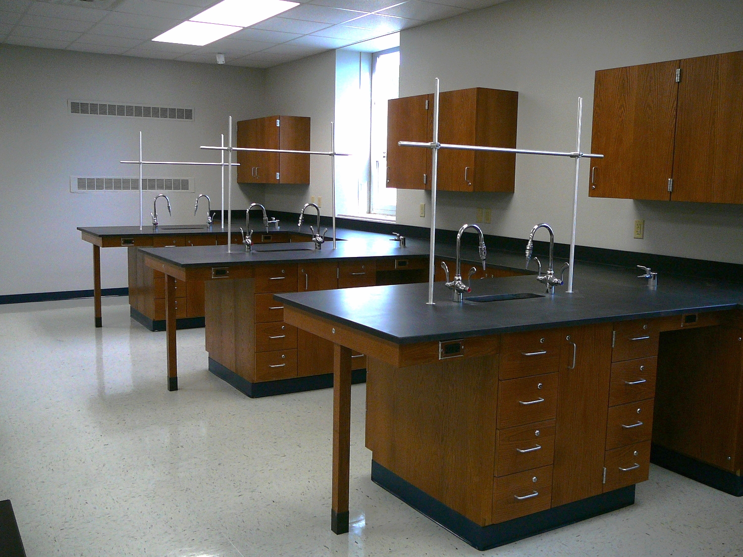
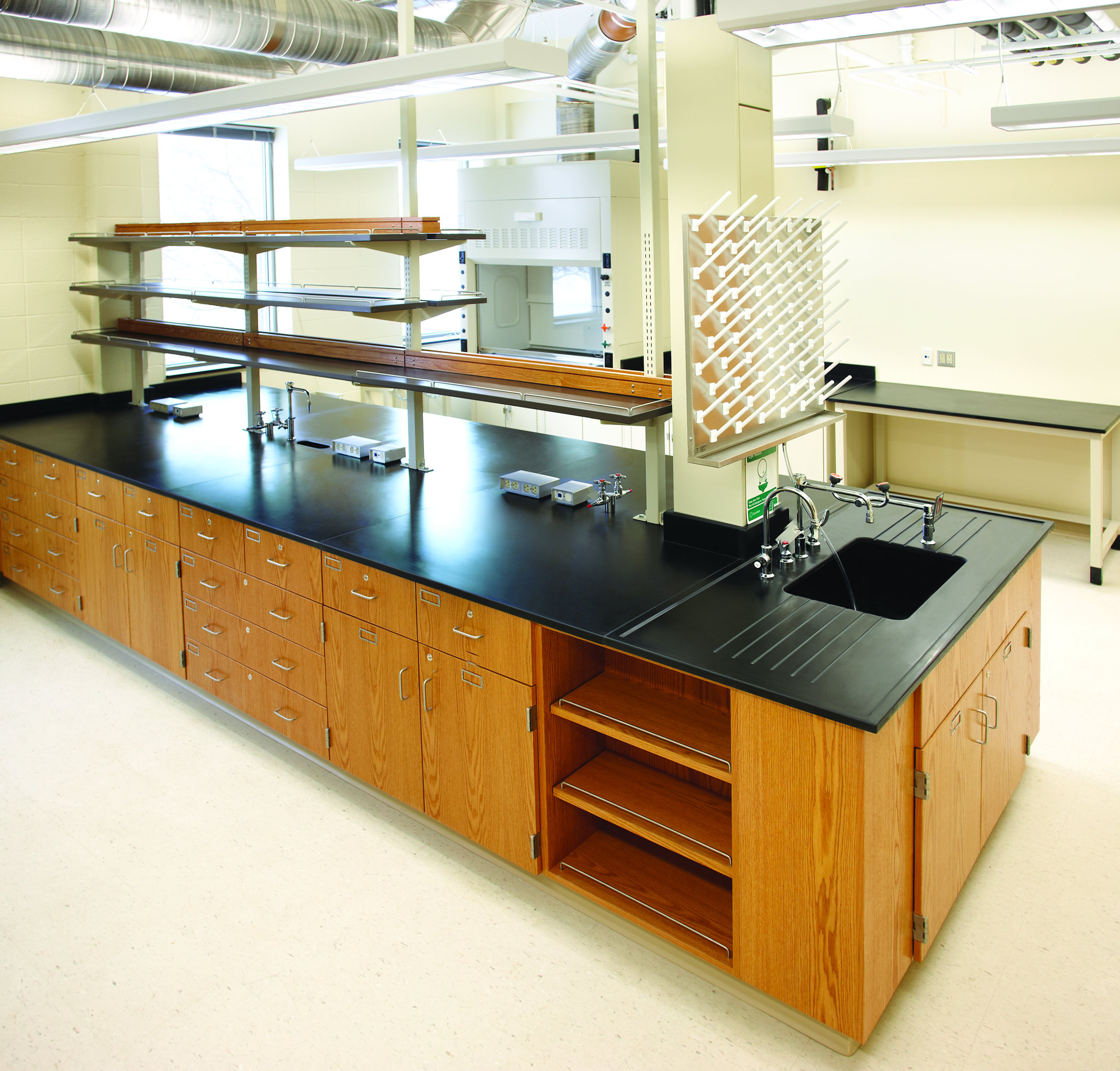
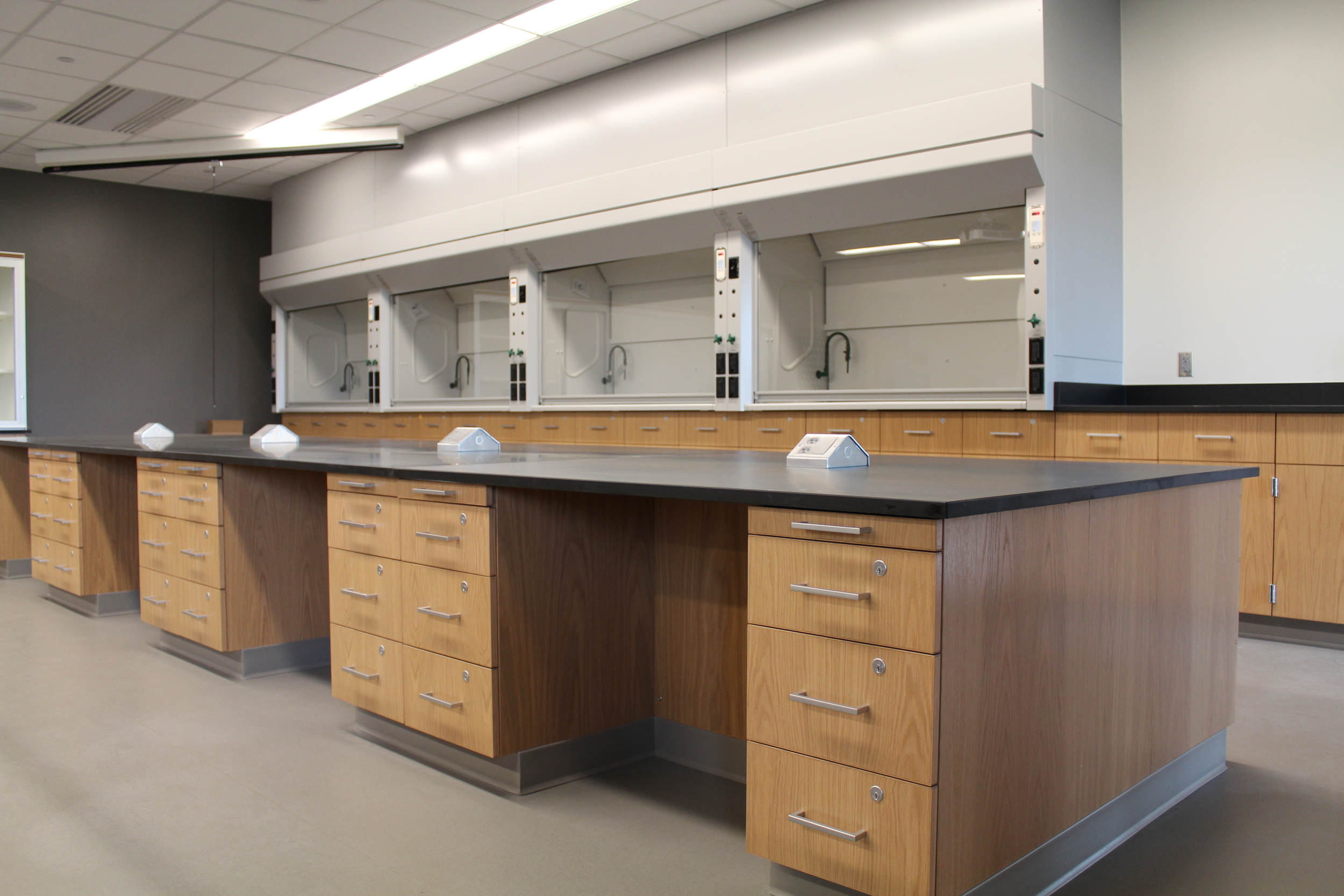
WOOD LABORATORY CASEWORK
PART 1: GENERAL
1.1 SECTION INCLUDES
A. Modular Wood Casework
B. Mobile Modular Wood Casework
C. Countertops
D. Shelving
E. Plumbing Fixtures
F. Electrical Fixtures
1.2 RELATED SECTIONS
A. Division 06 Section 10 00, “Rough Carpentry and Wall Blocking”
B. Division 09 Section 65 13, “Resilient Base and Accessories”
C. Division 11 Section 53 00, “Laboratory Equipment”
D. Division 12 Section 31 00, “Manufactured Metal Casework”
E. Division 12 Section 36 00, “Countertops”
F. Division 22 Section 40 00, “Plumbing Fixtures”
G. Related Work To Be Performed By Others:
1. Final installation of all plumbing, service and electrical fixtures attached to casework or countertop (excluding piping and wiring within fume hoods).
2. Final connection to service lines of all plumbing, service and electrical fixtures attached to laboratory casework or furniture.
1.3 REFERENCES
A. AWI: Quality Standards, Eighth Edition
B. SEFA 8: Laboratory Furniture – Casework, Shelving and Tables Guidelines
Science Equipment and Furniture Association (SEFA)
C. HPVA: Hardwood Plywood Veneer Association
D. ISO 9001:2000 – Quality Management
International Standards Organization (ISO)
E. Forest Stewardship Council
F. ADA (ATBCB ADAAG) Americans with Disabilities Act Accessibility Guidelines
Americans with Disabilities Act (ADA)
1.4 SYSTEM DESCRIPTION
A. Cabinet and Casework Area Design:
1. Full flush overlay [standard, OL1] type cabinets shall consist of hinges mortised into doors producing 1/8” reveal between intra-cabinet members and 1/16” reveal from cabinet front to cabinet side to provide a 1/8” reveal throughout.
2. Revealed overlay [option, OL2] type cabinets shall consist of a 1/8” reveal between intra-cabinet members and 1/4” reveal from cabinet fronts to cabinet sides to provide a 1/2” reveal between cabinets.
3. Veneer grain on door and drawer fronts are to be matched vertically per door/drawer set.
4. Veneer species shall be grade ‘A’ red oak [or Selected Specie]
[Selected Species] – Maple, Birch, Beech, Cherry, Bamboo, Sapele, or Others
5. Veneer cut shall be plain sliced [or Selected Cut depending on Selected Specie]
[Selected Cuts] – Rift Cut, Quarter Cut, Rotary Cut, European Steamed, Natural, Caramelized, Ribbon Stripe Quartered, or Others
6. Veneers shall be book matched, [or selected pattern]
[Selected Pattern] – Slip Matched, or Others
7. Doors and drawer fronts are to be slightly eased at all edges.
8. Cabinet elevations will be built in symmetrical sizes as required to fill the area.
9. Exposed veneer includes wood surfaces that are in plain sight when all cabinet doors and drawers are closed. In cases of no doors or drawers, or glass doors the line of plain sight is above 37” from the floor and below 72” from the floor.
1.5 SUBMITTALS
Refer to Section 01 33 00, “Submittal Procedures,” for requirements, procedures, etc.
A. Product Data:
1. Drawings shall include data and details for construction of the laboratory casework as well as information regarding the name, quantity, type and construction of materials (such as hardware, etc.), that will be used to complete the project.
B. Shop Drawings:
1. The laboratory casework manufacturer shall furnish shop drawings illustrating the layout and placement of all laboratory casework and fume hoods as well as any products included in this section.
2. Indicate the type and location of all service fittings and associated supply connections.
3. Preparation instructions and recommendations.
4. Storage and handling requirements and recommendations.
5. Installation methods.
C. Selection Samples:
Submit the following:
1. Samples for Selection: Manufacturer's standard sample collection.
2. One unit of each type of exposed hardware.
3. One (1) 24” wide, full-height base cabinet: Construction to consist of one (1) drawer, one (1) door, one (1) cupboard with adjustable full depth shelf and related hardware (pulls, hinges, drawer slides, etc.), complete with finish.
4. One 36” wide x 36” high wall cabinet: Construction to consist of two adjustable shelves as well as related hardware and doors, complete with finish.
5. One complete set of stain chips representing the manufacturer’s full range of available colors. Minimum sample size 2 inches by 3 inches.
D. Quality Assurance/Control
1. Design Data/Test Reports: Manufacturer shall submit test data and design criteria which are in compliance with the project specifications.
2. Certificates: All certifications required in the specifications shall be submitted with the original submittal package under separate cover. Certificates must be provided with the signature of a qualified individual of the supplier.
3. Manufacturers’ Instructions: Provide manufacturer’s instructions for installation and maintenance of all products provided and installed within this section.
1.6 QUALITY ASSURANCE
A. Manufacturer Qualifications:
The following list of information will be provide to the Architect at least ten (10) days prior to the bid opening:
1. List of manufacturing facilities;
2. A list of ten (10) installations of comparable stature completed by their workforce within the past 5 years;
3. Construction details depicting the materials, sizes and methods of construction;
4. Independent laboratory test reports that include information on cabinets, fume hoods and table top
finish and performance.
B. Mock-Ups
1. Area mockups shall be as indicated on the shop drawings. Post bid mockup areas must be priced for disassembly and reassembly and used within the project.
2. Do not proceed with remaining work until installation is approved by Architect.
a) Base cabinets installed with specified hardware.
b) Wall cabinets installed with specified hardware.
c) Workstations installed.
d) Fume hoods installed.
1.7 DELIVERY, STORAGE AND HANDLING
A. Packaging, Shipping, Handling and Unloading
1. Packaging: Products shall have packaging adequate enough to protect finished surfaces from soiling or damage during shipping, delivery and installation.
2. Delivery: Casework delivery shall only take place after painting, utility rough-ins and related activities are completed that could otherwise damage, soil or deteriorate casework in installation areas.
3. Handling: Care, such as the use of proper moving equipment, experienced movers, etc., shall be used at all times to avoid damaging the casework. Until installation takes place, any wrapping, insulation or other method of protection applied to products from the factory will be left in place to avoid accidental damage.
B. Acceptance at Site:
1. Casework will not be delivered or installed until the conditions specified under Part 3, Installation section of this document have been met. Products delivered to sites that are not enclosed and/or improperly conditioned will not be warranteed against warping or damage due to unsatisfactory conditions.
C. Storage:
1. Casework shall be stored in the area of installation. If, prior to installation, it is necessary for casework to be temporarily stored in an area other than the installation area, the environmental conditions shall meet the environmental requirements specified under the Project Site Conditions article of this section.
D. Waste Management and Disposal:
1. The supplier of the laboratory casework is responsible for removing any waste or refuse resulting from the installation of, or work pertaining to laboratory casework; thereby leaving the project site clean and free of debris. Trash container(s) to be provided by others.
1.8 WARRANTY
A. Furnish a written warranty that Work performed under this Section shall remain free from defects as to materials and workmanship for a period of one (1) year from date of shipment. Defects in materials and workmanship that may develop within this time are to be replaced without cost or expense to the Owner.
Defects include, but are not limited to:
1. Ruptured, cracked, or stained coating
2. Discoloration or lack of finish integrity
3. Cracking or peeling of finish
4. Slippage, shift, or failure of attachment to wall, floor, or ceiling
5. Structural failure
6. Warping or unloaded deflection of components
7. Failure of hardware
B. The warranty with respect to products of another manufacturer sold by Mott Manufacturing is limited to the warranty provided by Mott Manufacturing. Products from another manufacturer that have longer warranty’s than offered by Mott Manufacturing can be redeemed through the other manufacturer directly.
PART 2 – PRODUCTS
2.1 MANUFACTURER
A. Acceptable Manufacturer:
Mott Manufacturing LLC.; 562 Industrial Park Rd. Maxwelton, WV, USA 24957. Tel: (519) 752-7825. Fax: (519) 752-2895. Email: inquire@mott.ca, www.mott.ca.
B. Substitutions:
Must meet all specification requirements and have prior approval.
C. Requests for substitutions:
All requests will be considered in accordance with provisions of Section 01 60 00.
2.2 MATERIALS
A. Laboratory Casework:
1. Solid Lumber Used:
a) All hardwoods shall be carefully and thoroughly air-dried, and then kiln dried to a moisture content of 6 percent before use. This moisture content shall be maintained throughout production.
b) All front exterior wood casework surfaces exposed to view after installation, shall be plain sliced red oak [or Selected Specie and Selected Cut] grade ‘A’.
c) All door interiors, exposed exterior ends, tops and bottoms of open cases or cases having glazed doors; shall be plain sliced red oak [or Selected Species and Selected Cut] grade ‘A’ or comparable to it.
d) Some interior parts fabricated of hardwood shall be plain sliced red oak [or Selected Species grade ‘B’].
B. Exposed Veneer:
1. The veneer shall be specifically hand selected prior to fabrication of the cabinet faces and exposed components for uniformity of color and grain. The resulting selection shall provide a pleasing uniform color with natural characteristics selected to not interfere with the overall aesthetic appearance of the casework.
2. Veneer used for exterior surfaces exposed to view after installation, and the exposed interior ends, tops and bottoms of open cases shall be constructed of Grade ‘A’ or comparable, plain sliced red oak [or Selected Specie and Selected Cut].
3. Deviations and clarifications of HPVA standards.
4. Color and matching. 100% heartwood, no sapwood for red oak [Selected Species may have different wood characteristics, example: maple is 100% sapwood, no heartwood], no sharp contrasts at veneer joints.
5. Manufacturing characteristics. Rough cut or ruptured grain is not allowed.
6. All Door and drawer fronts will be vertically grain matched per door/drawer sets except where combination matched has been specified.
C. Semi-Exposed Veneer:
1. Veneer faces used for semi-exposed areas shall be constructed of red oak [or Select Species and Selected Cut], grade B, random matched.
2. Interior shelves shall be edge banded with 1/8 inch red oak [or Selected Specie and Selected Cut] hardwood on front edge.
D. Plywood Core Construction for Casework Body and Interiors:
1. All Plywood panels shall be constructed of minimum .”, 7-ply veneer core plywood or medium density particle board. Plywood used for shelving over 36” shall be of minimum 9-ply 1” thick.
E. Tempered Hardboard:
1. Wood-fiber and resin combination formed with heat and pressure into a hard, smooth surface.
2.3 SPECIAL MATERIALS
A. Glass:
1. Glass for framed doors shall be 1/8 inch float glass (1/4 inch thick on all floor cases and base cabinets) [or Selected Glass].
2. Glass for unframed sliding glass doors shall be 1/4 inch.
[Selected Glass] – Clear Laminated Safety, Tempered
2.4 CABINET CONSTRUCTION
A. Face Style [OL1]: Full flush overlay door and drawer faces with 1/8” reveal vertically and horizontally between door and/or drawer faces. 1/16” between door and/or drawer faces and the end panel of a cabinet.
B. Face Style [OL2]: Revealed door and drawer faces with 1/8” reveal vertically and horizontally between door and/or drawer faces. 1/4” between door and/or drawer faces and the end of a cabinet.
C. Cabinet Ends: .” Veneer core with 1/8” hardwood edge band of the same species as the cabinet face veneer.
D. Support Rails: Top rail (front), and intermediate rails between drawers shall be panel product veneer core 1” thick by 4” doweled into cabinet side panels. Front rail shall be edge banded with 1/8” hardwood edge band. Back rails (top & bottom) shall be panel product veneer core 3/4” thick by 6-5/8” dowelled into cabinet side panels.
E. Security Panels: Shall be between all locking doors or drawers and vertically adjacent drawers when locks are specified as keyed differently.
F. Toe Space Rail: .” Veneer core fastened to the cabinet via dowels
G. Cabinet Bottoms: .” Veneer core with a 1/8” hardwood edge band set flush and attached to cabinet ends via dowels.
H. Cabinet Backs: Fully removable .” tempered hardboard [or Selected Back].
1. Optional on drawer cabinets per architect
2. Mandatory on cabinets with doors
3. Sink cabinets to have a partial back to allow for plumbing, etc.
[Selected Backs] – Veneer Core
I. Vertical Dividers: Full height dividers and half height dividers shall be . inch material of same species and grade as cabinet body, secured to the bottom of the cabinet and top rails with dowels. Exposed edges shall be edge banded to match casework.
J. Shelves: 1” Veneer core [or Selected Shelf Option] edge banded on cabinets with 32mm spacing to be set on [steel pin type shelf support or twin pin plastic seismic shelf supports]. Full depth shelves are standard and shall come to within .” of the face of the cabinet in open units and within .” to the inside face of cabinet doors.
[Selected Shelf Options] - .” Veneer core ≤36” Wide Shelves, Powder Coated Steel, 304 Stainless Steel
[Selected Shelf Depth] – Half, Split
K. Drawer Body: Drawer sides to be constructed from .” thick 9-ply Baltic Birch [or Selected Drawer Material]. Drawer sides shall be attached via dovetail joints at all four corners. Bottom shall be .” tempered hardboard and shall be captured in all four sides of the drawer body and glued completely around the bottom.
[Selected Drawer Material] – Powder Coated Steel, 304 Stainless Steel, Veneer Core
L. Door and Drawer Fronts: .” Particleboard core [or Selected Front Core] banded on all sides with same specie veneer edge banding.
[Selected Front Core] – MDF, Combo Core
2.5 WALL AND FLOOR CASES
A. Case Ends: .” Veneer core with 1/8” hardwood edge band of the same species as the cabinet face veneer
B. Tops and Bottoms of Floor and Wall Cases: 1” Thick veneer core with 1/8” edge banding of same species as cabinet on front edges. Tops and bottoms are fastened to end panels via dowel pins.
C. Backs: 1/4” Veneer core screwed in back panels
D. Fixed Center Shelf on Floor Cases: 1” Veneer core with matching veneer edge banding on exposed edges on all open, hinged, and sliding door cabinets. Fixed center shelves fastened to ends via dowel pin construction.
E. Shelves: 1” Veneer core [or Selected Shelf Option] edge banded on cabinets. Full depth shelves are standard and shall come to within .” of the face of the cabinet in open units and within .” to the inside face of cabinet doors.
[Selected Shelf Options] - .” Veneer core ≤36” Wide Shelves, Powder Coated Steel, 304 Stainless Steel
[Selected Shelf Depth] – Half, Split
F. Solid Doors:
1. .” Particleboard core [or Selected Front Core] banded on all sides with same specie veneer edge banding.
[Selected Front Core] – MDF, Combo Core
2. Provide two hinges on all doors up to 36" in height and a minimum of three hinges on any doors exceeding this height.
G. Framed Glazed Doors:
1. Hinged Doors: .” Solid lumber shaped to accept 1/8” float glass [or Selected Glass] on wall cabinets. Glass to be .” float glass [or Selected Glass] on floor cabinets.
2. Provide two hinges on all doors up to 36” in height and a minimum of three hinges on any doors exceeding this height.
3. Sliding Doors: Provide doors that slide in top channels with a nylon wheel operating on an inset plastic track.
4. Hold glass in place with a removable plastic panel retainer to facilitate change of damaged glass.
[Selected Glass] – Clear Laminated Safety, Tempered
H. Unframed Sliding Glass Doors
1. Unframed sliding doors to be 1/4” float glass [or Selected Glass] with all edges ground, set in an extruded aluminum shoe with nylon wheel assemblies and top and bottom extruded aluminum track.
2. Provide silencer guides fitting on top of glass panel for smooth and noiseless operation.
3. Grind pull handles into sliding glass door.
[Selected Glass] – Clear Laminated Safety, Tempered MOTT WOOD SPEC REV-9 1/14 12 35 53-Wood 10
2.6 HARDWARE
A. Pulls:
1. Door and drawer pulls shall be brushed aluminum wire type [or Selected Handle Type and Selected Handle Material] mounted vertically on doors and horizontally on drawers. Two pulls shall be required on all drawers over 24 inches wide.
[Selected Handle Types] – Recessed, Full Width
[Selected Handle Material] – Black Matte Plastic, Stainless Steel, Aluminum, Chrome
B. Hinges:
Hinges shall be five (5) knuckle 2 . inch grade ‘1’ dull chrome type [or Selected Hinge Finish, or Selected Hinge Type] for all hinged doors. Two hinges for doors less than 48 inches in height and three hinges on doors 48 inches or above in height.
[Selected Hinge Finish] – 304 Stainless Steel, Bright Chrome, Black, Powder Coated, Customer Specified
[Selected Hinge Type] – Overlay, European Concealed 165°, Barrel Style
C. Door Catches:
1. Roller Catches: Shall be used on all hinged doors (European concealed, and 8 barrel hinges excluded). Catches shall have a spring-loaded polyethylene roller and are provided with a steel strike plate. Double doors without locks shall have a catch on each door. Tall cases shall have latching devices located on upper and lower part of each door. On cabinets equipped with locks, the left-hand door shall have a positive catch and the right hand door shall have roller type catch.
2. Elbow Catches: Catches and strike plates shall be used on left hand doors of double door cases where locks are used, and shall be steel, cadmium plated.
D. Locks:
Locks shall be provided on casework drawers and hinged doors when indicated by the specified product number, shown on the drawings or called for in the casework schedule. Exposed surface of locks shall be dull chrome plated. All locks, for the purpose of coordinating keying systems, shall be five (5) disc tumbler type with removable cores [or Selected Lock]. Locks are keyed individually [or Selected Keying Schedule] unless otherwise specified to be furnished with master keys, grand master keying is not provided unless specified prior to bidding time.
1. Framed Glass Doors: Locks shall be plunge type sliding showcase locks which are to be of the same type as those selected above.
2. Sliding Glass Doors: Locks shall be ratchet type sliding showcase locks which are to be of the same type as those selected above.
[Selected Lock] – Pin, 5-Pin, 3-Level Keying
[Selected Keying Schedule] – Keyed Alike, Keyed in Groups per Room, Master Key MOTT WOOD SPEC REV-9 1/14 12 35 53-Wood 11
E. Drawer Slides:
1. Drawer slides for standard drawers shall be grade ‘1’ 100 lbs ball bearing full extension type [or Selected Slide].
[Selected Slides] - 200 lbs Rated – Full Extension Type – Zinc Plated
- 200 lbs Rated – Full Extension Type with Soft/Self-Close Feature – Zinc Plated
- 200 lbs Rated – Full Extension Type with Soft/Self-Close Feature – Zinc Plated
F. Shelf Support Clips:
Shelf support clips shall be [single steel pin, or plastic twin pin seismic type], for mounting on interior of cabinets. Clips shall be corrosion resistant and shall retain shelves from accidental removal. Shelves are adjustable on 1-1/4” centers.
G. Mobile Cabinets:
Mobile cabinets shall be provided with four caster wheels and brakes in lieu of the 4” toe kick. Cabinets with multiple drawers will automatically include a drawer interlock to prevent multiple drawers from being opened at once and therefore causing the cabinet to tip. Counterweights shall be installed to prevent drawers holding 50 lbs from tipping the cabinet.
2.7 TABLES
A. Construction
1. Provide standard height table aprons of not less than .” x 3-. ” solid lumber machined to receive corner blocks and bolted to 2-1/8” x 2-1/8” solid hardwood legs. Drawers shall be constructed and finished as cabinet drawers as noted above.
2. Provide all table legs with leveling devices and black plastic shoes unless otherwise specified. Shoes are to conceal leveling devices. Shoes shall be 4” high and constructed of plastic.
2.8 SPECIAL UNITS
A. Acid Storage Base Cabinet:
a) Cabinet exterior is to match type of wood, stain, color and finish of adjacent cabinetry but is to be lined with a removable corrosion resistant material (molded polyethylene). Venting is to be accomplished through the use of a polyethylene vent hose through the back of the cabinet. If size permits, cabinet shall be equipped with one black phenolic shelf. Front edge of cabinet bottom shall have a 1” high raised sill to contain spills. Provide the door with a decal signifying “ACID” storage. On acid cabinets with two doors, provide one decal signifying “ACID” storage on each door.
B. Flammable Cabinet:
1. UL1275 compliant: Flammable cabinets shall be listed and labeled as to having passed the testing requirements specified by Underwriters Laboratories.
2. NFPA 30 compliant: Flammable cabinets shall be designed in such a way to meet or exceed the NFPA 30 standard.
3. Cabinet Construction:
a. Cabinet end panels, top, bottom and back shall be 1” thick meeting the same veneer quality requirements as indicated in section 2.2 with 1/8” hardwood edge banding. The entire structure including end panels, top, bottom and back shall be of rabbet joint construction with each joint secured from two directions with countersunk screws affixed to hardwood blocking from the interior of the cabinet. The unit will be equipped with and a keyed astragal to seal the interior of the cabinet from the outside. All base units shall have a removable steel drip tray recessed within the blocking capable of retaining a 2” depth of spilled liquid.
b. Doors: Doors shall be fabricated using 1” solid plywood core. All four edges shall be edge banded with 1/8” hardwood. When the cabinet utilizes two doors the mutual joint shall consist of a rabbet overlap of not less than 1”. Provide overlaid red warning decal 50mm (2”) high on doors as follows: "FLAMMABLE -- KEEP FIRE AWAY".
4. Cabinet exterior: To match type of wood, stain, color and finish of adjacent cabinetry but is subject to the following differences:
a. Inset Overlay: Doors are set within the members of the frame to allow for the creation of a near airtight seal when closed. Reveals reflect panel width and are 1” around the entire face of the cabinet.
b. Exposed Plywood: Properties pertaining to plywood used for exterior surfaces and doors remain consistent with the properties already specified under the Exposed Plywood section of Laboratory Casework.
c. Door Pull & Catch: Door pulls and catches shall be part of an integrated three point latching system that will remain functional in the event of fire exposure.
d. Hinges: Full-length piano style hinges are to be used that will not lose their load capability in the event of fire exposure.
e. Vents: Two 50mm (2”) vents, complete with fire baffle covers on each vent, with 50mm (2”) dia. fine metal filter shall be provided in the rear of the cabinet, one near the top of the cabinet and one near the bottom of the cabinet.
2.9 FINISHES
A. Flat Line Finish System
1. Finish must meet SEFA 8 requirements.
2. All exposed exterior and interior surfaces shall be finished with an environmentally friendly coating. The finish shall be applied to the wood under controlled conditions prior to the casework being assembled and attachment of hardware. The finish shall be fully UV cured to ensure proper performance.
B. Chemical Resistance Performance
1. Test Procedure:
Method A: Test volatile chemical by placing a cotton ball saturated with reagent in the mouth of a 1-ounce bottle and inverting the bottle on the surface of the panel.
Method B: Test non-volatile chemicals by placing five drops of the reagent on the surface of the panel and covering with a 24 mm watch glass, convex side down.
Note: Chemical Resistance for each reagent was rated as
Level 0= No detectable change
Level 1= Slight change in color or gloss
Level 2= Slight surface etching or severe staining
Level 3= Pitting, crate ring, swelling, or erosion of coating (Obvious and significant deterioration).
For a finish to pass, there should be no more than four level 3 results.
N/A= No reagent in the lab
2. Test Results
CHEMICAL SPOT TEST (SEFA 8-W) Test No- Chemical
Test Method
Level
1. Amyl Acetate
A
0
2. Ethyl Acetate
A
0
3. Acetic Acid, 98%
A
0
4. Acetone
B
0
5.Acid Dichromate, 5%
A
0
6. Butyl Alcohol
A
0
7. Ethyl Alcohol
A
0
8. Methyl Alcohol
B
0
9.Ammonium Hydroxide, 28%
A
1
10. Benzene
A
0
11. Carbon Tetrachloride
A
0
12. Chloroform
A
0
13. Chromic Acid, 60%
B
0
14. Cresol
A
0
15. Dichloroacetic Acid
A
0
16. Dimethylformamide
A
0
17.Dioxane
A
0
18. Ethyl Ether
A
0
19. Formaldehyde, 37%
A
0
20. Formic Acid, 90%
A
0
21. Furfural
B
0
22. Gasoline
A
0
23. Hydrochloric Acid, 37%
B
0
24. Hydrofluoric Acid, 48%
B
1
25. Hydrogen Peroxide, 3%
B
0
26. Tincture of Iodine
B
1
27. Methyl Ethyl Ketone
A
0
28. Methylene Chloride
A
0
29. Monochlorobenzene
A
0
30. Naphthalene
A
N/A
31. Nitric Acid, 20%
B
0
32. Nitric Acid, 33%
B
0
33. Nitric Acid, 70%
B
34. Phenol, 90%
A
N/A
35. Phosphoric Acid, 85%
B
0
36. Silver Nitrate, saturated
B
0
37. Sodium Hydroxide, 10%
B
1
38. Sodium Hydroxide, 20%
B
1
39. Sodium Hydroxide, 40%
B
1
40. Sodium Hydroxide, flake
B
1
41. Sodium Sulfide, saturated
B
1
42. Sulfuric Acid, 33%
B
0
43. Sulfuric Acid, 77%
B
1
44. Sulfuric Acid, 96%
B
3
45. Sulfuric Acid, 77% and Nitric Acid, 70% (1:1)
B
3
46. Toluene
A
0
47. Trichloroethylene
A
0
48. Xylene
A
0
49. Zinc Chloride, saturated
B
0
PART 3 – EXECUTION
3.1 INSTALLERS
A. Installer Qualifications:
1. Installer shall have a minimum of 5 years continued experience in installation or application of systems similar to those required for this project.
2. Installer shall be authorized by either the distributor or manufacturer. Warranty will be void if unauthorized installer executes the installation.
3.2 EXAMINATION
A. Site Verification of Conditions:
1. Casework will not be delivered or installed until the following conditions have been met:
a) Building must be enclosed (windows and doors sealed and weather-tight);
b) An operational HVAC system that maintains temperature and humidity at occupancy levels must be in place;
c) Ceiling, overhead ductwork and lighting must be installed;
d) Site must be free of further construction such as “wet work”;
e) Required backing and reinforcements must be installed accurately and the project must be ready for casework installation.
B. NOTE:
In the event that any of the specified requirements for installation are not present at the time of requested delivery, the general contractor or owner must provide the casework manufacturer with a letter of deviation that releases the manufacturer from any responsibility or liability from any damage to the products resulting from the unfavorable building conditions.
3.3 INSTALLATION
A. Casework Installation:
1. Casework shall be set with components plumb, straight and square, securely anchored to building structure with no distortion. Concealed shims shall be used as required.
2. Cabinets in continuous runs shall be fastened together with joints flush, uniform and tight with misalignment of adjacent units not to exceed 1/16 of an inch.
3. Wall casework shall be secured to walls that are structural enough to withstand load capacity required by cabinets.
4. Top edge surfaces shall be abutted in one true plane. Joints are to be flush and gap shall not exceed 1/8 of an inch between tops units.
5. Casework and hardware shall be adjusted and aligned to allow for accurate connection of contact points and efficient operation of doors and drawers without any warping or binding.
B. Countertop Installation:
1. Countertops are to have been fabricated in lengths according to drawings, with ends abutting tightly and sealed with corrosion resistant sealant.
2. Tops will be anchored to base casework in a single true plane with ends abutting at hairline joints with no raised edges at joints.
3. Joints shall be factory prepared having no need for in-field processing of top and edge surfaces.
4. Joints shall be dressed smoothly, surface scratches removed and entire surface cleaned thoroughly.
3.4 CLEANING
A. Ensure all products are unsoiled and match factory finish. Remove or repair damaged or defective units.
B. Clean all finished surfaces, including drawers and cabinet shelves, and touch up as necessary.
C. Countertops shall be cleaned and free of grease or streaks.
3.5 PROTECTION:
A. Counter tops and ledges shall be protected with 1/4 inch ribbed cardboard for the remainder of the construction process.
B. Examine casework for damaged or soiled areas; replace, repair, and touch-up as required.
C. Touch-up, repair or replace damaged products before Substantial Completion.