SPECIFICATIONS
SUSPENDED AVION SERVICE CARRIER
PART 1 – GENERAL
Summary:
This Specification identifies the minimum material and construction standards that are required to
deliver a quality installation of steel overhead service carriers. Service carriers shall be supplied in
accordance with the requirements of this Specification. The service carriers identified in this Specification
shall include the miscellaneous metal panels and other related components as identified on the Drawings
and that are necessary for the complete installation.
1.1 SECTION INCLUDES
A. Overhead Service Carrier Body
B. Overhead Service Carrier Post Assembly
1.2 RELATED SECTIONS
A. Division 11 Section 53 00, “Laboratory Equipment”
B. Division 22 Section 40 00, “Plumbing Fixtures”
C. Division 26 Section 05 00, “Common Work Results for Electrical”
D. Division 23 Section 05 00, “Common Work Results for HVAC”
E. Related Work To Be Performed By Others:
1. Final installation of all plumbing, service and electrical fixtures attached to overhead
service carriers.
2. Final connection to service lines of all plumbing, service and electrical fixtures attached to
overhead service carriers.
1.3 ALTERNATE PROPOSALS
A. Proposals are invited from alternate manufacturers only if they comply with the minimum design
requirements and the minimum performance requirements.
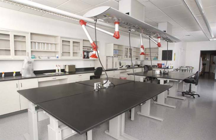
1.4 SYSTEM DESIGN REQUIREMENTS
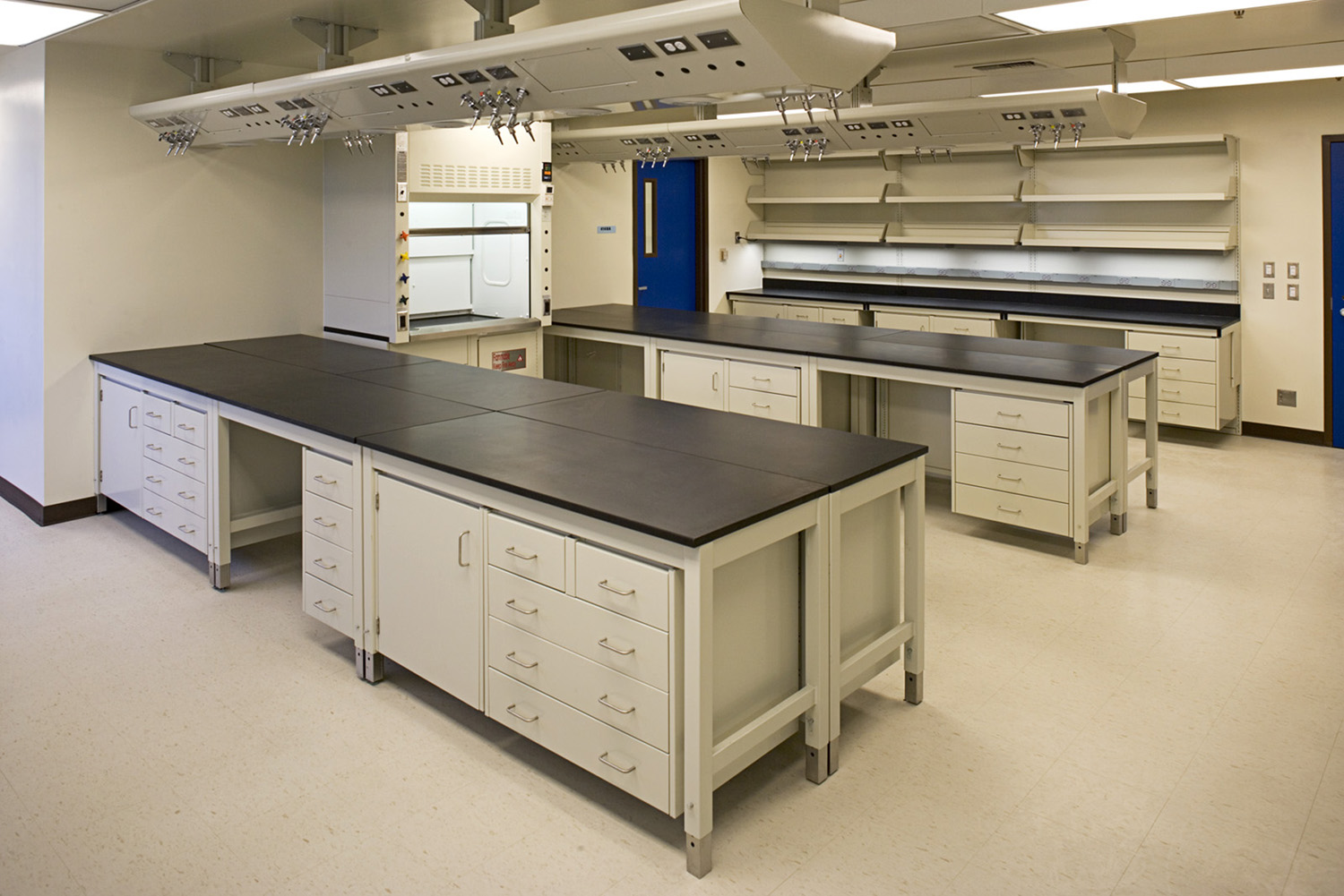
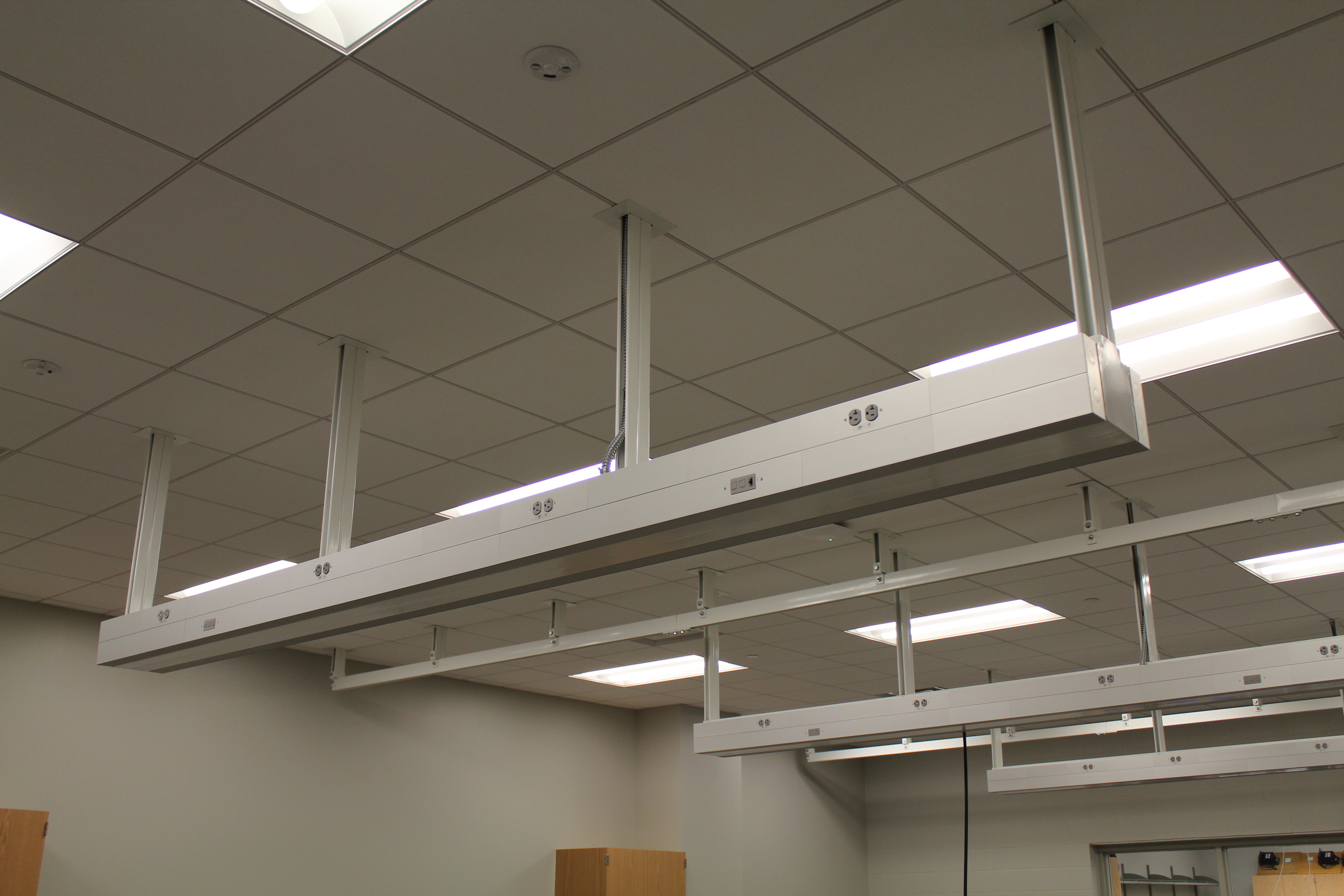
A. Horizontal service chase ties into the ceiling deck and is suspended below the ceiling t-grid.
B. Heavy-Duty Vertical Uprights: Enclosed support structure for horizontal service carrier that shall
house all plumbing, electrical and data lines.
C. Carrier body shall serve as a service chase for all cabling, plumbing, electrical conduit, light
fixtures and localized exhaust ductwork.
1. Modular units shall be suitable for floor-mounted cabinets, freestanding tables and mobile
equipment racks.
2. Mobile carrier bodies can be ganged side-to-side.
3. Equipped with hinged top dust covers for ease of utility access, visual inspection and utility
shut-offs.
D. System requirements:
1. Independently supported overhead storage components.
2. Modular units can be linked in tandem for a continuous service run.
3. Horizontal chase can be supplied with quick connects and disconnects for mobile bench
and/or equipment rack applications.
4. Service carrier can be suspended at any height above specified work surface to free
workspace of service fixtures, electrical and teledata outlets.
1.5 SUBMITTALS
A. Shop Drawings: Provide 3/4"=1'-0" scale elevations of all components, cross sections, rough-in
and anchor placements, tolerances and clearances. Provide 1/4"= 1'-0" rough-in plan drawings for
coordination with trades. Rough in shall show free area.
Include number of each type of submittal required if this information is not
covered in Division 1 or elsewhere.
1.6 QUALITY ASSURANCE
A. Single source responsibility: Laboratory furniture system, casework, work surfaces, laboratory
equipment, chemical fume hoods and accessories shall be manufactured or furnished by a single
laboratory furniture company.
B. Manufacturer's qualifications: Modern plant with proper tools, dies, fixtures and skilled workmen to
produced high quality laboratory horizontal service chase and equipment, and shall meet the
following minimum requirements:
1. Five years or more experience in manufacture of laboratory equipment of type specified.
2. Ten installations of equal or larger size and requirements.
1.7 DELIVERY, STORAGE AND HANDLING
A. Schedule delivery of laboratory furniture system so that spaces are sufficiently complete that
material can be installed immediately following delivery.
B. Protect finished surfaces from soiling or damage during handling and installation.
1.8 PROJECT CONDITIONS
A. Do not deliver or install equipment until the following conditions have been met:
1. Windows and doors are installed and the building is secure and weather tight.
2. Ceiling, overhead ductwork and lighting are installed.
3. All painting is completed and floor tile is installed.
PART 2 – PRODUCTS
2.1 MANUFACTURER
A. Design, materials, construction and finish of product specified are the minimum acceptable
standard of quality for the Overhead Service Carrier. The basis of this specification is Mott
Manufacturing Limited, Brantford, Ontario, Canada
2.2 OVERHEAD SERVICE CARRIER
A. General requirements for carriers:
1. Carrier body, light covers and hinged dust covers shall be fabricated from 20-gauge cold
rolled steel. Removable end panels shall be fabricated from 11-guage cold rolled steel.
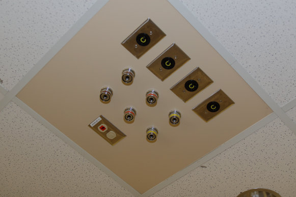
2. Carrier body shall incorporate UL approved, factory installed junction boxes for electrical
and teledata outlets. Electrical and teledata outlets to be field installed.
3. Carrier body shall also incorporate factory punched and plugged service ports. Service
fixtures to be field installed.
4. Finish: Chemical resistant powder paint finish in manufacturer's standard color to be
selected.
5. Carrier horizontal section shall be equipped with optional hinged top covers to provide
access to services and prevent dust from entering the top of the carrier.
B. Carrier body:
1. Nominal overhead service carrier dimensions:
a. Width: [24”] [30”] [36"] [48"] [60"] [72”]
b. Depth: [22”]
c. Height: [6"]
2. Interior service bracket: Support bracket of 14-gauge cold rolled steel that can accept
attachment brackets for copper and conduit service lines.
3. Carrier body end covers shall be provided only when end of overhead service carrier is
exposed.
4. Carrier bottom shall be smooth without removable panels and shall be punched as
required to accept lighting, plumbing and local exhauster mounting.
2.3 CEILING POST ASSEMBLIES
A. General requirements for ceiling post assemblies, ceiling extension assemblies structures:
1. Vertical structural support: 16-gauge cold rolled vertical chase. Complete with vertical
15/16” x 1-7/8” unistrut supports extending 18” above the top of the carrier’s vertical
support enclosure. Final connection to the above ceiling structure to be made by the
mechanical contractor.
2. Nominal height options: [48”]
2.4 FINISHES
A. Metal finish to be as in Appendix 1 - Laboratory Steel Furniture Finish.
PART 3 – EXECUTION
3.1 INSTALLATION
A. Furniture system installation:
1. Install system in strict accordance with manufacturer's instructions.
2. Set system components plumb, square, and straight with no distortion and securely
anchored to building structure.
3. Overhead Service Carriers are supported by the building structure. Anchorage design is a
field condition and local building engineers must be consulted and their instructions
complied with.
B. Install Overhead Service Carrier and accessory items per Section 12 35 53.
3.2 ADJUSTING
A. Repair or remove and replace defective work, as directed by [Architect] [Owner] upon completion
of installation.
3.3 CLEANING
A. Clean shop finished laboratory Overhead Service Carrier system and touch up as required.
3.4 PROTECTION OF FINISHED WORK
A. Provide all necessary protective measures to prevent exposure of laboratory Overhead Service
Carrier system and attached components from exposure to other construction activity.
B. Advise contractor of procedures and precautions for protection of material, installed laboratory
Overhead Service Carrier system, and fixtures from damage by work of other trades.
MOTT/SIGMA SPEC REV-1 10/06 12 31 00.1-1
SECTION 12 31 00.1
(FORMERLY 12310.7)
Manufactured Metal Casework
SUSPENDED CHAMELEON SERVICE CARRIER
PART 1 – GENERAL
Summary:
This Specification identifies the minimum material and construction standards that are required to
deliver a quality installation of steel overhead service carriers. Service carriers shall be supplied in
accordance with the requirements of this Specification. The service carriers identified in this Specification
shall include the miscellaneous metal panels and other related components as identified on the Drawings
and that are necessary for the complete installation.
1.1 SECTION INCLUDES
A. Overhead Service Carrier Body
B. Overhead Service Carrier Post Assembly
C. Overhead Service Carrier Filler Panel Assembly
1.2 RELATED SECTIONS
A. Division 11 Section 53 00, “Laboratory Equipment”
B. Division 22 Section 40 00, “Plumbing Fixtures”
C. Division 26 Section 05 00, “Common Work Results for Electrical”
D. Division 23 Section 05 00, “Common Work Results for HVAC”
E. Related Work To Be Performed By Others:
1. Final installation of all plumbing, service and electrical fixtures attached to overhead
service carriers.
2. Final connection to service lines of all plumbing, service and electrical fixtures attached to
overhead service carriers.
1.3 ALTERNATE PROPOSALS
A. Proposals are invited from alternate manufacturers only if they comply with the minimum design
requirements and the minimum performance requirements.
1.4 SYSTEM DESIGN REQUIREMENTS
A. Horizontal service chase ties into the ceiling deck and is suspended below the ceiling t-grid.
B. Heavy-Duty Vertical Uprights: Support structure for cantilevered shelves with ceiling extension
assemblies that can height adjust the horizontal carrier body for different working heights.
C. Carrier body shall serve as a service chase for all cabling, plumbing, electrical conduit, light
fixtures and localized exhaust ductwork.
1. Modular units shall be suitable for floor-mounted cabinets, freestanding tables and mobile
equipment racks.
2. Mobile carrier bodies can be ganged side-to-side.
3. Equipped with easy to remove entry covers for ease of utility access, visual inspection and
utility shut-offs.
D. System requirements:
1. Independently supported overhead storage components.
2. Vertical height of shelves can be adjusted with simple, but positive mechanisms.
3. Modular units can be linked in tandem for a continuous service run.
4. Horizontal chase can be supplied with quick connects and disconnects for mobile bench
and/or equipment rack applications.
5. Service carrier can be suspended at any height above specified work surface to free
workspace of service fixtures, electrical and teledata outlets.
1.5 SUBMITTALS
Include number of each type of submittal required if this information is not
covered in Division 1 or elsewhere.
A. Shop Drawings: Provide 3/4"=1'-0" scale elevations of all components, cross sections, rough-in
and anchor placements, tolerances and clearances. Provide 1/4"= 1'-0" rough-in plan drawings for
coordination with trades. Rough in shall show free area.
1.6 QUALITY ASSURANCE
A. Single source responsibility: Laboratory furniture system, casework, work surfaces, laboratory
equipment, chemical fume hoods and accessories shall be manufactured or furnished by a single
laboratory furniture company.
B. Manufacturer's qualifications: Modern plant with proper tools, dies, fixtures and skilled workmen to
produced high quality laboratory horizontal service chase and equipment, and shall meet the
following minimum requirements:
1. Five years or more experience in manufacture of laboratory equipment of type specified.
2. Ten installations of equal or larger size and requirements.
1.7 DELIVERY, STORAGE AND HANDLING
A. Schedule delivery of laboratory furniture system so that spaces are sufficiently complete that
material can be installed immediately following delivery.
B. Protect finished surfaces from soiling or damage during handling and installation.
1.8 PROJECT CONDITIONS
A. Do not deliver or install equipment until the following conditions have been met:
1. Windows and doors are installed and the building is secure and weather tight.
2. Ceiling, overhead ductwork and lighting are installed.
3. All painting is completed and floor tile is installed.
PART 2 – PRODUCTS
2.1 MANUFACTURER
A. Design, materials, construction and finish of product specified are the minimum acceptable
standard of quality for the Overhead Service Carrier. The basis of this specification is Mott
Manufacturing Limited, Brantford, Ontario, Canada
2.2 OVERHEAD SERVICE CARRIER
A. General requirements for carriers:
1. Carrier body and inside/outside access covers shall be fabricated from 20-gauge cold
rolled steel.
2. Carrier body shall incorporate UL approved, factory installed junction boxes for electrical
and teledata outlets. Electrical and teledata outlets to be field installed.
3. Carrier body shall also incorporate factory punched and plugged service ports. Service
fixtures to be field installed.
4. Finish: Chemical resistant powder paint finish in manufacturer's standard color to be
selected.
5. Carrier horizontal section shall be equipped with removable top covers to provide a flat
upper surface capable of supporting storage cabinets.
B. Carrier body:
1. Nominal overhead service carrier dimensions:
a. Width: [24”] [30”] [36"] [48"] [60"] [72”]
b. Depth: [24”] [32”]
c. Height: [8.5"]
2. Capable of vertical adjustment in one-inch increments.
3. Interior service bracket: Support bracket of 14-gauge cold rolled steel that can accept
attachment brackets for copper and conduit service lines.
4. Carrier body end covers shall be provided only when end of overhead service carrier is
exposed.
5. Carrier bottom shall be smooth without removable panels and shall be punched as
required to accept lighting, plumbing and local exhauster mounting. Carrier angled sides
shall be equipped with removable access panels held in place with plastic friction catches.
6. Lamp assemblies shall consist of 50 watt halogen recessed fixtures. Total quantity shall
be 72” unit: 3; 48” unit :2; 24” unit: 1.
7. Lamp assemblies can be rebulbed by a bottom removal of the fixture assembly.
Accessibility from the body interior is not acceptable.
8. Load bearing capabilities:
a. Total overhead service carrier plus 400 pounds per unit.
b. Shelf unit plus 100 to 180 pounds respective of size.
2.3 CEILING POST ASSEMBLIES
A. General requirements for ceiling post assemblies, ceiling extension assemblies structures:
1. Vertical structural support: 16-gauge cold rolled vertical shall integrate a slotted standard
to cantilevered components.
2. Nominal height options: [36”][48”][60”]
3. Ceiling gusset assemblies include a set of two gussets to provide a means to attach to the
ceiling deck or structural support. Ceiling gusset shall be an integral part of the vertical
support and shall be 11-gauge cold rolled steel.
4. Optional filler panel assemblies shall provide an umbilical chase between the ceiling
plenum and horizontal chase.
5. A set of two optional filler panels shall enclose the space between the ceiling posts.
Nominal dimensions:
a. Length: [24”][30”][36”][48"][60"][72”]
b. Height: up to 72” to suit site conditions.
2.4 SHELVES
A. General requirements for shelves:
1. Shelf brackets: 16-gauge cold rolled steel.
2. Vertical shelf adjustment: One-inch increments.
3. Depth and weight capacity: [12”–180 lbs., 18”–130 lbs., 24”–100 lbs.]
B. Outside Shelf:
1. Nominal dimensions:
a. Length: [24”][30”][36”][48"][60"][72”]
2. Shelf bracket shall be designed to prevent accidental release from upright.
2.5 FINISHES
A. Metal finish to be as in Appendix 1 - Laboratory Steel Furniture Finish.
3 – EXECUTION
3.1 INSTALLATION
A. Furniture system installation:
1. Install system in strict accordance with manufacturer's instructions.
2. Set system components plumb, square, and straight with no distortion and securely
anchored to building structure.
3. Overhead Service Carriers are supported by the building structure. Anchorage design is a
field condition and local building engineers must be consulted and their instructions
complied with.
B. Install Overhead Service Carrier and accessory items per Section 12 35 53.
3.2 ADJUSTING
A. Repair or remove and replace defective work, as directed by [Architect] [Owner] upon completion
of installation.
3.3 CLEANING
A. Clean shop finished laboratory Overhead Service Carrier system and touch up as required.
3.4 PROTECTION OF FINISHED WORK
A. Provide all necessary protective measures to prevent exposure of laboratory Overhead Service
Carrier system and attached components from exposure to other construction activity.
B. Advise contractor of procedures and precautions for protection of material, installed laboratory
Overhead Service Carrier system, and fixtures from damage by work of other trades.
MOTT/SIGMA SPEC REV-0 10/09 12 31 00.1-1
SECTION 12 31 00.1
(FORMERLY 12310.7)
Manufactured Metal Casework
SUSPENDED STRATUS SERVICE CARRIER
PART 1 – GENERAL
Summary:
This Specification identifies the minimum material and construction standards that are required to
deliver a quality installation of steel overhead service carriers. Service carriers shall be supplied in
accordance with the requirements of this Specification. The service carriers identified in this Specification
shall include the miscellaneous metal panels and other related components as identified on the Drawings
and that are necessary for the complete installation.
1.1 SECTION INCLUDES
A. Overhead Service Carrier Body
B. Overhead Service Carrier Post Assembly
1.2 RELATED SECTIONS
A. Division 11 Section 53 00, “Laboratory Equipment”
B. Division 22 Section 40 00, “Plumbing Fixtures”
C. Division 26 Section 05 00, “Common Work Results for Electrical”
D. Division 23 Section 05 00, “Common Work Results for HVAC”
E. Related Work To Be Performed By Others:
1. Final installation of all plumbing, service and electrical fixtures attached to overhead
service carriers.
2. Final connection to service lines of all plumbing, service and electrical fixtures attached to
overhead service carriers.
1.3 ALTERNATE PROPOSALS
A. Proposals are invited from alternate manufacturers only if they comply with the minimum design
requirements and the minimum performance requirements.
1.4 SYSTEM DESIGN REQUIREMENTS
A. Horizontal service chase ties into the ceiling deck and is suspended below the ceiling t-grid.
B. Heavy-Duty Vertical Uprights: Enclosed support structure for horizontal service carrier that shall
house all plumbing, electrical and data lines.
C. Carrier body shall serve as a service chase for all cabling, plumbing, electrical conduit, light
fixtures and localized exhaust ductwork.
1. Modular units shall be suitable for floor-mounted cabinets, freestanding tables and mobile
equipment racks.
2. Mobile carrier bodies can be ganged side-to-side.
3. Equipped with hinged top dust covers for ease of utility access, visual inspection and utility
shut-offs.
D. System requirements:
1. Modular units can be linked in tandem for a continuous service run.
2. Horizontal chase can be supplied with quick connects and disconnects for mobile bench
and/or equipment rack applications.
3. Service carrier can be suspended at any height above specified work surface to free
workspace of service fixtures, electrical and teledata outlets.
1.5 SUBMITTALS
A. Shop Drawings: Provide 3/4"=1'-0" scale elevations of all components, cross sections, rough-in
and anchor placements, tolerances and clearances. Provide 1/4"= 1'-0" rough-in plan drawings for
coordination with trades. Rough in shall show free area.
Include number of each type of submittal required if this information is not
covered in Division 1 or elsewhere.
1.6 QUALITY ASSURANCE
A. Single source responsibility: Laboratory furniture system, casework, work surfaces, laboratory
equipment, chemical fume hoods and accessories shall be manufactured or furnished by a single
laboratory furniture company.
B. Manufacturer's qualifications: Modern plant with proper tools, dies, fixtures and skilled workmen to
produced high quality laboratory horizontal service chase and equipment, and shall meet the
following minimum requirements:
1. Five years or more experience in manufacture of laboratory equipment of type specified.
2. Ten installations of equal or larger size and requirements.
1.7 DELIVERY, STORAGE AND HANDLING
A. Schedule delivery of laboratory furniture system so that spaces are sufficiently complete that
material can be installed immediately following delivery.
B. Protect finished surfaces from soiling or damage during handling and installation.
1.8 PROJECT CONDITIONS
A. Do not deliver or install equipment until the following conditions have been met:
1. Windows and doors are installed and the building is secure and weather tight.
2. Ceiling, overhead ductwork and lighting are installed.
3. All painting is completed and floor tile is installed.
PART 2 – PRODUCTS
2.1 MANUFACTURER
A. Design, materials, construction and finish of product specified are the minimum acceptable
standard of quality for the Overhead Service Carrier. The basis of this specification is Mott
Manufacturing Limited, Brantford, Ontario, Canada
2.2 OVERHEAD SERVICE CARRIER
A. General requirements for carriers:
1. Carrier body, light covers and hinged dust covers shall be fabricated from 20-gauge cold
rolled steel.
2. Removable end panels shall be fabricated from cast aluminium.
3. Carrier body shall incorporate UL approved, factory installed junction boxes for electrical
and teledata outlets. Electrical and teledata outlets to be field installed.
4. Carrier body shall also incorporate factory punched and plugged service ports. Service
fixtures to be field installed.
5. Finish: Chemical resistant powder paint finish in manufacturer's standard color to be
selected.
6. Carrier horizontal section shall be equipped with optional hinged top covers to provide
access to services and prevent dust from entering the top of the carrier.
B. Carrier body:
1. Nominal overhead service carrier dimensions:
a. Width: [24”] [30”] [36"] [48"] [60"] [72”]
b. Depth: [22”]
c. Height: [6"]
2. Interior service bracket: Support bracket of 14-gauge cold rolled steel that can accept
attachment brackets for copper and conduit service lines.
3. Carrier body end covers shall be provided only when end of overhead service carrier is
exposed.
4. Carrier bottom shall be smooth without removable panels and shall be punched as
required to accept lighting, plumbing and local exhauster mounting.
2.3 CEILING POST ASSEMBLIES
A. General requirements for ceiling post assemblies, ceiling extension assemblies structures:
1. Vertical structural support: 16-gauge cold rolled vertical chase. Complete with vertical
15/16” x 1-7/8” unistrut supports extending 18” above the top of the carrier’s vertical
support enclosure. Final connection to the above ceiling structure to be made by the
mechanical contractor.
2. Nominal height options: [48”]
2.4 FINISHES
A. Metal finish to be as in Appendix 1 - Laboratory Steel Furniture Finish.
PART 3 – EXECUTION
3.1 INSTALLATION
A. Furniture system installation:
1. Install system in strict accordance with manufacturer's instructions.
2. Set system components plumb, square, and straight with no distortion and securely
anchored to building structure.
3. Overhead Service Carriers are supported by the building structure. Anchorage design is a
field condition and local building engineers must be consulted and their instructions
complied with.
B. Install Overhead Service Carrier and accessory items per Section 12 35 53.
3.2 ADJUSTING
A. Repair or remove and replace defective work, as directed by [Architect] [Owner] upon completion
of installation.
3.3 CLEANING
A. Clean shop finished laboratory Overhead Service Carrier system and touch up as required.
3.4 PROTECTION OF FINISHED WORK
A. Provide all necessary protective measures to prevent exposure of laboratory Overhead Service
Carrier system and attached components from exposure to other construction activity.
B. Advise contractor of procedures and precautions for protection of material, installed laboratory
Overhead Service Carrier system, and fixtures from damage by work of other trades.